
User Manual

CAUTION: Heating speed selection MUST be adjusted
to provide proper temperature rise as specified on the
rating plate. Failure to adjust the heating speed may
shorten heat exchanger life.
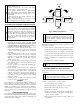
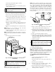
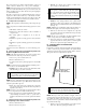
14. Turn on electrical supply. Manually close blower access
panel door switch. Use a piece of tape to hold switch closed.
Check for proper rotation and speed changes between
heating and cooling by jumpering R to G and R to Y on
control center thermostat terminals. (See Fig. 12.)
WARNING: Blower access panel door switch opens
115-v power to control center. No component operation
can occur. Caution must be taken when manually closing
this switch for service purposes. Failure to follow this
warning could result in electrical shock, personal injury,
or death.
15. If furnace is operating properly, release blower access panel
door switch, replace blower access panel, and replace main
furnace door.
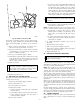
III. CLEANING BURNERS
The following items should be performed by a qualified service
technician. If the burners develop an accumulation of light dirt or
dust, they may be cleaned by using the following procedure:
1. Turn off gas and electrical supplies to furnace.
2. Remove main furnace door.
3. Remove burner box cover.
4. Using backup wrench, disconnect gas supply pipe from gas
valve.
5. Remove wires from gas valve. Note location for reassem-
bly.
CAUTION: Label all wires prior to disconnection when
servicing controls. Wiring errors can cause improper and
dangerous operation.
6. Remove burner box pressure tube from gas valve regulator
fitting.
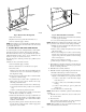
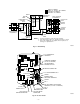
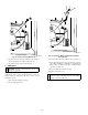
7. Remove screws that secure manifold to burner box. (See
Fig. 5.)
8. Remove manifold, orifices, and gas valve as 1 assembly.
9. Remove screws attaching burner assembly in burner box.
10. Remove burner assembly from burner box.
NOTE: All burners are attached to burner bracket and can be
removed as 1 assembly.
11. Clean burners with soft brush and vacuum.
12. Reinstall manifold, orifice, and gas valve assembly in
burner box. Ensure manifold seal grommet is installed
properly and burners fit over orifices.
13. Reconnect wires to gas valve. Refer to furnace wiring
diagram for proper wire location.
14. Reinstall burner box pressure tube to gas valve regulator
fitting.
15. Reinstall gas supply pipe to gas valve using backup wrench
on gas valve to prevent rotation and improper orientation.
NOTE: Use propane gas resistant pipe dope to prevent gas leaks.
DO NOT use Teflon tape.
WARNING: Gas valve switch or knob MUST be facing
forward or tilted upward. Failure to follow this warning
could result in property damage, personal injury, or death.
16. Replace burner box cover.
17. Turn on gas and electrical supplies to furnace.
18. Check for gas leaks.
WARNING: Never use matches, candles, flame, or
other sources of ignition to check for gas leakage. Use a
soap-and-water solution. Failure to follow this warning
could result in a fire, personal injury, or death.
19. Replace main furnace door.
IV. CLEANING HEAT EXCHANGERS
The following items should be performed by a qualified service
technician.
A. Primary Heat Exchangers
If the heat exchangers get an accumulation of light dirt or dust on
the inside, they may be cleaned by the following procedure:
NOTE: If the heat exchangers get a heavy accumulation of soot
and carbon, both the primary and secondary heat exchangers
should be replaced rather than trying to clean them thoroughly due
to their intricate design. A build-up of soot and carbon indicates
that a problem exists which needs to be corrected, such as
improper adjustment of manifold pressure, insufficient or poor
quality combustion air, improper vent termination, incorrect size
or damaged manifold orifice(s), improper gas, or a restricted heat
exchanger (primary or secondary). Action must be taken to correct
the problem.
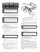
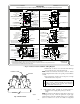
TABLE 1—SPEED SELECTOR
COLOR SPEED
FACTORY
ATTACHED TO
Black High Cool
Yellow (When Present) Medium High Spare
Blue Medium Low Heat
Red Low Spare
White Common Com
Fig. 5—Burner Box Assembly
A93295
MANIFOLD
MOUNTING
SCREW
MANIFOLD
GAS VALVE
REGULATOR
FITTING
GAS VALVE
—4—