
User Manual
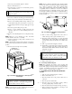

1. Turn off gas and electrical supplies to furnace.
2. Remove main furnace door.
3. Disconnect wires or connectors to rollout switch, gas valve,
ignitor, and flame sensor.
CAUTION: Label all wires prior to disconnection when
servicing controls. Wiring errors can cause improper and
dangerous operation.
4. Disconnect combustion-air intake pipe from intake housing.
5. Remove the pressure switch tube from intake housing.
6. Remove screws attaching intake housing to burner box, and
rotate intake housing away from burner box for removal.
7. Using backup wrench, disconnect gas supply pipe from gas
valve.
8. Disconnect pressure tubing from gas valve.
9. Remove 2 screws attaching top filler panel and rotate
upwards to gain access to screws attaching burner box to
cell panel.
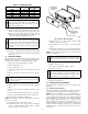
10. Remove screws attaching burner box to cell panel. (See Fig.
5.)
NOTE: Burner box cover, manifold, gas valve, and burner
assembly should be removed as 1 assembly.
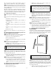
11. Clean heat exchanger openings with a vacuum and a soft
brush. (See Fig. 6.)
NOTE: After cleaning, inspect the heat exchangers to ensure they
are free of all foreign objects that may restrict flow of combustion
products.
12. Reverse items 4 through 10 for reassembly.
WARNING: The ground wire from the gas valve MUST
be attached to the burner box attachment screw. Failure to
attach this ground wire to an adequate casing ground will
cause the furnace control to lock out.
NOTE: Be sure burner box gasket is installed between burner box
and cell panel. If gasket is damaged, replace it.
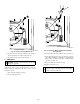
NOTE: Inspect combustion-air intake housing. If foamed gasket
was removed, check for any damage. If gasket is damaged in any
way, it must be repaired. To repair, remove damaged gasket
section, apply sealant releasing agent such as PAM cooking spray
or equivalent (must not contain corn or canola oil, aromatic or
halogenated hydrocarbons or inadequate seal may occur) to burner
box and apply a small bead of G.E. RTV 162, G.E. RTV 6702, or
Dow-Corning RTV 738 sealant to edge of combustion-air intake
housing. (See Fig. 7.)
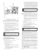
13. Refer to furnace wiring diagram and connect wires to
rollout switch, gas valve, ignitor, and flame sensor.
14. Reconnect pressure switch tubes to gas valve and intake
housing. Refer to tube routing label on main furnace door
for proper tube location. Be sure tubes are not kinked. (See
Fig. 8.)
15. Turn on gas and electrical supplies to furnace.
16. Check furnace operation through 2 complete heat operating
cycles. Look through sight glass in burner enclosure to
check burners. Burner flames should be clear blue, almost
transparent. (See Fig. 9.)
17. Check for gas leaks.
WARNING: Never use matches, candles, flame, or
other sources of ignition to check for gas leakage. Use a
soap-and-water solution. Failure to follow this warning
could result in a fire, personal injury, or death.
18. Replace main furnace door.
B. Secondary Heat Exchangers
NOTE: The condensing side (inside) of the secondary heat
exchangers CANNOT be serviced or inspected. A small number of
bottom outlet openings can be inspected by removing the inducer
assembly. See Flushing Collector Box and Drainage System
section for details on removing inducer assembly.
V. FLUSHING COLLECTOR BOX AND DRAINAGE
SYSTEM
1. Turn off gas and electrical supplies to furnace.
2. Remove main furnace door.
3. Disconnect inducer motor and pressure switch wires or
connectors.
4. Disconnect pressure switch tubes.
5. Disconnect vent pipe from inducer housing outlet by
loosening coupling clamp on inducer outlet.
6. Disconnect drain tube from inducer housing. (See Fig. 8.)
7. Remove inducer housing assembly by removing 4 bolts
attaching assembly to cell panel.
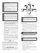
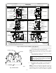
Fig. 6—Cleaning Inlet Openings of Primary Heat
Exchangers
A93080
PRIMARY HX
INLET OPENINGS
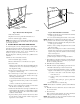
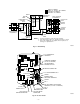
Fig. 7—Combustion-Air Intake Housing Gasket
Repair
A93087
PAM
RTV
—5—
→