
User Manual
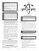
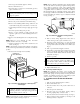
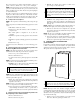

hydrocarbons or inadequate seal may occur) to inducer housing.
(See Fig. 10.) Apply a small bead of G.E. RTV 162, G.E. RTV
6702, or Dow-Corning RTV 738 sealant to groove in collector
box.
11. Refer to furnace wiring diagram and connect wires to
inducer motor and pressure switch or connectors.
12. Reconnect pressure tubes to pressure switch. See diagram
on main furnace door for proper location of tubes. Be sure
tubes are not kinked. (See Fig. 8.)
13. Turn on gas and electrical supplies to furnace.
14. Check furnace operation through 2 complete heat operating
cycles. Check area below inducer housing, vent pipe, and
condensate trap to ensure no condensate leaks occur. If
leaks are found, correct the problem.
15. Check for gas leaks.
WARNING: Never use matches, candles, flame, or
other sources of ignition to check for gas leakage. Use a
soap-and-water solution. Failure to follow this warning
could result in a fire, personal injury, or death.
16. Replace main furnace door.
VI. SERVICING HOT SURFACE IGNITOR
The ignitor does NOT require annual inspection. Check ignitor
resistance before removal.
1. Turn off gas and electrical supplies to furnace.
2. Remove main furnace door.
3. Disconnect ignitor wire connection.
4. Check ignitor resistance.
a. Using an ohm meter, check resistance across both ignitor
leads in connector.
b. Cold reading should be between 45 ohms and 90 ohms.
c. If ohm reading is higher than 110 ohms, ignitor is
cracked and must be replaced.
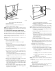
5. Remove ignitor assembly.
a. Do not remove ignitor from bracket while assembly is in
furnace. Using a 1/4 in. nutdriver, remove screw secur-
ing bracket and ignitor assembly to bottom of burner
box. The screw in the bracket is always located toward
outside of burner box. The screw may be hidden by inlet
box or inlet pipe, but can be removed without removing
either. After removing screw, slide ignitor and bracket
toward outside of burner box and pull straight out.
CAUTION: The ignitor is fragile. DO NOT allow it to
hit the side of the burner box opening while removing or
replacing it.
b. Inspect ignitor for a white area indicating a crack may be
present. If found, replace ignitor.
NOTE: A small crack cannot be seen on a new ignitor. After a
period of operation, a white area will be visible around the crack.
c. If replacement is required, replace ignitor on ignitor
bracket external to furnace to avoid damage as the
silicon portion is very brittle and will easily crack or
shatter.
d. To remove ignitor from ignitor bracket, remove screw
holding ignitor ceramic block to bracket and pull ce-
ramic block out of bracket.
6. To replace ignitor/ignitor assembly, reverse items 5a
through 5d.
7. Reconnect ignitor wire connection.
8. Turn on gas and electrical supplies to furnace.
9. Verify ignitor operation by initiating control board self-test
feature or by cycling thermostat.
10. Replace main furnace door.
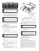
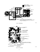
VII. ELECTRICAL CONTROLS AND WIRING
CAUTION: There may be more than 1 electrical supply
to the unit. Check accessories and cooling unit for
additional electrical supplies.
The electrical ground and polarity for 115-v wiring must be
maintained properly. Refer to Fig. 11 for field wiring information
and to Fig. 15 for unit wiring information.
NOTE: If the polarity is not correct, the STATUS LED on the
control center will flash rapidly and prevent the furnace from
operating. The control system also requires an earth ground for
proper operation of the control center and flame sensing.
The 24-v circuit contains an automotive-type, 3-amp fuse located
on the control center. (See Fig. 12.) Any direct shorts of the 24-v
wiring during installation, service, or maintenance will cause this
fuse to blow. If fuse replacement is required, use ONLY a fuse of
identical size.
With power to the unit disconnected, check all electrical connec-
tions for tightness. Tighten all screws on electrical connections. If
any smoky or burned connections are found, disassemble the
connection, clean all parts, strip wire, and reassemble properly and
securely.
Reconnect electrical supply to unit and observe unit through 1
complete operating cycle. Electrical controls are difficult to check
without proper instrumentation; if there are any discrepancies in
the operating cycle, contact your dealer and request service.
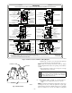
VIII. TROUBLESHOOTING
For an explanation of fault codes, refer to service label located on
back of main furnace door or Fig. 16, and the Troubleshooting
Guide.
Fig. 10—Gasket on Collector Box
A93081
RTV
PAM
—7—