
User Manual

The control center stores 1 fault code (the last fault to occur) for a
period of 48 hrs or until the 115- or 24-v power is interrupted.
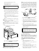
NOTE: Removing blower access panel will open blower access
panel door switch and terminate 115-v power to control center, and
fault code will be erased. Look into blower access panel sight glass
for current LED status.
The unit’s component test is a useful troubleshooting tool since it
displays the current status (fault code) of the furnace and func-
tionally operates all furnace components except the gas valve. The
component test and methods to initiate it are described below.
A. Component Test Sequence
NOTE: All components are functionally operated except the gas
valve.
When component test is initiated, the following sequence of events
occurs:
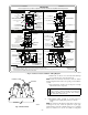
1. LED flashes a fault code 4 times.
2. Inducer motor starts and continues to run for remainder of
component test.
3. Hot surface ignitor is energized for 15 sec, then de-
energized.
4. Main blower operates at cooling speed for 10 sec, then turns
off.
5. Main blower operates at heating speed for 10 sec, then turns
off.
6. Inducer motor stops.
Component test can be initiated by one of the following proce-
dures.
B. Initiating Component Test and Retrieving Fault Code
By Removing Main Limit Switch Wire
NOTE: NO thermostat signal may be present at control center
and all blower time delay off periods must be completed.
1. Leave 115-v power to furnace turned on.
2. Remove main furnace door.
3. Look into blower access panel sight glass for current LED
status.
NOTE: Leave blower access panel installed to maintain power to
control center to view current LED status.
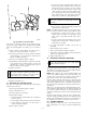
4. BRIEFLY remove either wire from the main limit switch
until the LED goes out, then reconnect it.
CAUTION: Make sure limit switch wire does not con-
tact any metallic component such as the gas valve. If wire
is shorted, 3-amp fuse on control center will blow.
NOTE: If wire to main limit is disconnected longer than 4 sec, the
control senses limit circuit is open. Main blower will start and
retrieval request will be ignored.
5. When above items have been completed, the component
test sequence will occur as described in the Component Test
Sequence section above.
NOTE: Be sure to record the fault code which is flashed 4 times
at start of component test for further troubleshooting.
6. After component test is completed and LED is ON continu-
ously indicating the furnace is ready to operate when a
signal from the thermostat is received, replace main furnace
door.
C. Initiating Component Test and Retrieving Fault Code
By Jumpering Control TEST Terminal
1. Remove main furnace door.
2. Remove blower access panel.
3. Manually close blower access panel door switch. Use a
piece of tape to hold switch closed.
WARNING: Blower access panel door switch opens
115-v power to control center. No component operation
can occur. Caution must be taken when manually closing
this switch for service purposes. Failure to follow this
warning could result in electrical shock, personal injury,
or death.
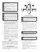
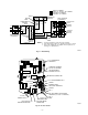
4. BRIEFLY short (jumper) TEST, 1/4-in. quick-connect
terminal on control center (adjacent to the LED diagnostic
light) and the C
OM terminal on thermostat connection block.
(See Fig. 12.)
NOTE: If TEST to C
OM terminals are jumpered longer than 2 sec,
LED will flash rapidly, and retrieval request will be ignored.
5. When above items have been completed, the component
test sequence will occur as described in the Component Test
Sequence section above.
NOTE: Be sure to record the fault code which is flashed 4 times
at start of component test for further troubleshooting.
6. After component test is completed and furnace is operating
properly, release blower access panel door switch, replace
blower access panel, and replace main furnace door.
IX. CHECKING HEAT TAPE OPERATION
(IF APPLICABLE)
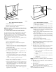
In applications where the ambient temperature around the furnace
is 32°F or lower, freeze protection measures are required. If this
application is where heat tape has been applied, check to ensure it
will operate when low temperatures are present.
NOTE: Heat tape, when used, should be wrapped around the
condensate drain trap and drain line. There is no need to use heat
tape within the furnace casing. Most heat tapes are temperature
activated, and it is not practical to verify the actual heating of the
tape. Check the following:
1. Check for signs of physical damage to heat tape such as
nicks, cuts, abrasions, gnawing by animals, etc.
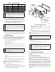
CAUTION: If this furnace is installed in an uncondi-
tioned space where the ambient temperatures may be
32°F or lower, freeze protection measures must be taken.
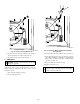
A93058
32°F MINIMUM INSTALLED
AMBIENT OR FREEZE
PROTECTION REQUIRED
—9—