B101 Norcold Repair Guide Models 442, 443, 452, 453, 462, 463, 482, 483 Table of Contents Page 3-2 General Information and Specification 3-3 Information About Electrical Connections 3-3 Description of Operation 3-4 Location of Control and Components 3-5 Lighting and Operating Instructions 3-6 High Humidity and Interior Lamp Switch 3-7 Parts Function 3-10 Troubleshooting Procedures 3-10 Refrigerator Will Not Ignite Electrically on Propane 3-12 Refrigerator Does Not Indicate that a Flame has been Establishe
B101 General Information and Specification OPERATING LIMITS - ALL MODELS AC Mode: 132 VAC Max., 108 VAC Min. 15.4 VDC Max., 10.5 VDC Min. DC Mode: 15.4 VDC Max., 11.5 VDC Min. Gas Mode: 11" W.C. Gas Supply 10.5" W.C. Min. Burner Pressure (High Fire) 15.4 VDC Max., 10.5 VDC Min. MODELS 442, 443 RATINGS 1050 Btu/Hr Input LP Gas Mode: 11" W.C.
B101 Information About Electrical Connection Electrical Connection 120 Volts AC-400 Series The refrigerator is equipped with a three prong plug for protection against shock hazard and must be connected into a recognized three prong attachment receptacle. The free length of cord is 24", so it is recommended that the receptacle be located to the left side of the refrigerator (viewed from rear) and approximately 12" from the floor. This allows easy accessibility through the vent door.
A008 Component Location and Identification (Single Door Models) A. Illuminated Ignition Switch B. Flame On Indicator Lamp C. Thermostat Control Knob D. Combination Control Knob 1. Gas On/Electric Interlock 2. Push-In Safety Valve E. AC/DC Mode Selector Switch (3-Way models only) F. Serial Identification Plate F A Figure 3.2 B C D E Controls Location, Single Door Model G Component Location and Identification (Two Door Models) A. Illuminated Ignition Switch B. Flame On Indicator Lamp C.
B101 Lighting and Operating Instructions Lighting Instructions: Gas Operation 1. Make certain that 12 Volts DC is available to the refrigerator. 2. Turn on gas supply at the tank. 3. Set thermostat control to the maximum cold setting. 4. Set ignitor switch to "ON" position. The light located on the switch will illuminate if 12 volts DC is present. 5. Push and turn the "ELEC-OFFGAS" control counter-clockwise so that knob indicator points to "GAS".
B101 High Humidity - Storage Switch Models 462, 463, 482, 483 Only Turning this switch to HIGH HUMIDITY will keep the surface between the door openings dry during high humidity conditions. This position will also allow the interior light to activate when the lower door is opened. The switch should be left in the NORMAL OPERATION position unless condensation is observed in this area. Both NORMAL and HIGH HUMIDITY positions allow the cabinet light to activate when the lower door is opened. Note: (Figure 3.
B101 Parts Function Combination Control The 400 Series refrigerators utilize a single combination control to determine and regulate the mode of operation (gas or electric). The control is operated by two knobs. The first is to select the operating mode (gas or electric), and the second is to control the thermostat setting. The control consists of a gas shut off valve, safety valve, thermostat and electric interlock. The interlock prevents the possibility of operating on gas and electric at the same time.
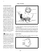
B101 Ground Connection Relighter Ignition Electrode Connection + 12 volt Connection Applies sparking power to the ignition electrode to light the burner and illuminates the flame indicator lamp when a flame is established. Indicator Light Connection Ignition Electrode Sends sparks to the burner to light the flame. Figure 3.9 Relighter Note: This Norcold is equipped with an electronic ignition relighter. It automatically relights the flame should it blow out.
B101 Burner Applies the correct amount of heat to the cooling unit, when it is supplied the correct amount of air and LP Gas. Figure 3.12B Burner AC Heating Element Applies the correct amount of heat to the cooling unit, when it is supplied with the correct AC voltage. All current 120 Volt AC heater will have black lead wires. Figure 3.13 AC Heater Figure 3.14 DC Heater DC Heating Element Applies the correct amount of heat to the cooling unit, when it is supplied with the correct DC voltage.
B101 Troubleshooting Procedures Refrigerator Will Not Ignite Electrically on Propane 1. Check for 12 Volts DC between positive and negative leads at the rear of the refrigerator. If not present, correct source. 12 Volt Supply Wires Figure 3.16 12 Volt Supply Check Figure 3.17 Fuse Continuity Check Figure 3.18 Controls Access 2. If 12 Volts DC is present, then check the 3 Amp fuse for continuity. If open, then replace with fuse of same size and rating. WARNING NEVER OVERFUSE A CIRCUIT.
B101 4. To check for loose wire connections, set your Volt-Ohm meter to + 25 Volt scale. Check for presence of 12 volts at the Ignitor rocker switch from the center wire of the switch to DC negative, as shown in Figure 3.19. If present, proceed to Step 5. Figure 3.19 12 Volt Check at Blue and White Terminals Figure 3.20 12 Volt Check at Orange and White Terminals 5. Check for 12 volts at the outlet of the Ignitor switch, making sure the switch is on.
B101 Refrigerator Indicates No Flame Established If the Flame Indicator is not illuminated, yet the Ignitor switch is ON with 12 volts available to unit and flame at burner, then check the following: 1. Keep in mind that the Flame Indicator will not illuminate unless a flame has been established. 2. Set VOM to + 5 Volts scale. You should read from 1.5 to 2 Volts DC at the terminals of the Relighter shown in Figure 3.23. If not, replace the Relighter. 3.
B101 Flame will not stay lit (Lights and Then Goes Out) 1. Remove the control knob and depress the shaft with your finger until it bottoms out as shown in Figure 3.25. If refrigerator ignites and stays lit realign the combination control and reinstall knob. If ignition does not occur, proceed to next step. 2. When the burner ignites and then goes out, this can be caused by (1) thermocouple not positioned properly in the flame or (2) retaining clip not properly installed. See Figure 3.26. 3.
B101 7. The adjacent chart specifies the maximum pressure (high fire) and minimum pressure (low fire) for the burner operation. The Combination Control modulates the pressure to the burner between this minimum/maximum range based on ambient temperature, refrigerator load, and thermostat setting. 8. Access to the combination control is gained by removing (2) knobs and (6) screws as shown in Figure 3.18. The Combination Control needs not be removed for the pressure check. 9.
B101 Refrigerator Overfreezing 1. With gas supply off, hook up your U-tube or gas manometer as shown. 2. A part which can cause this symptom is the combination control. 3. Remove the capillary tube from the fins. Place a cup of ice water on the top shelf of the refrigerator. Immerse the capillary tube in the ice water as shown in Figure 3.30. 4. If the pressure readings are not within the specifications as shown in the Gas Pressure chart, replace the combination control. 5.
B101 WARNING NEVER OVERFUSE A CIRCUIT. REPLACE BLOWN FUSE WITH EXACT REPLACEMENT INDICATED BY NORCOLD. OVERFUSING OF A CIRCUIT CAN RESULT IN A FIRE. Note: Before gaining access to the combination control, check the AC Heater element as described in Steps 14-18 on pages 3-17 & 3-18. 3. We must now gain access to the AC-ELEC STDBY-DC switch. This procedure only applies to 3-way models. On 2Way models proceed to Step 8.
B101 8. Check for 120 Volts at each terminal to ground of the combination control as illustrated in Figures 3.37 and 3.38. Normal readings should show 120 Volts on both terminals. 9. If there is 0 Volts on both terminals, check wiring connections. If there is 120 Volts on only one terminal, replace the Combination Control. If unit is a 2-Way, skip to Step 12. 10. Check for 120 Volts at Point 1 and ground and Point 2 and ground of switch as shown in Figure 3.35 (AC-ELEC STDBYDC switch is now set at AC). 11.
B101 16. If you read an open, the refrigerator will not cool and the heater element must be replaced. 17. If you have a reading, but it is less or greater than the specification, it indicates the element is not the correct size and must be replaced. 18. A shorted heater element will cause the 5 Amp fuse to blow. The Refrigerator will not Operate or Cool on DC Electric Figure 3.41 12 Volt Check at DC Supply Connections Figure 3.42 Checking F3 Fuse for Continuity Figure 3.
B101 5. If preceding checks did not reveal the cause of malfunction, then access to the control panel is required as shown in Figure 3.43. The first step in gaining access is to remove the two control knobs (A), then remove the (6) Phillips head screws (B) as shown. Once control panel has been removed, you need to remove (2) Phillips head screws (C). Then pull the control mounting bracket forward. This allows access to the controls. 6. Step 6, 7 & 8 apply to 3-Way units only.
B101 a 2-Way, skip to Step 13. 11. Check for 12 Volts at Points 1 and 2 of switch and ground as shown in Figure 3.44 (ACELEC STDBY-DC switch is now set at DC. 12. There should be 12 Volts at both Points 1 and 2. If not, and connections are checked as proper, replace AC-ELEC STDBY-DC switch. 13. Check for 12 volts at the DC heater terminals as shown in Figure 3.48. 14. If there is no 12 volt reading, a bad connection is indicated between the thermostat and heater terminals. 15.
B101 3-21
B101 3-22
B101 3-23
B101 3-24
B101 This Page Contains Information on Earlier Versions On earlier versions of 3-Way models, the control panels were built with a 2-Position AC-DC switch. Later models have a 3-Position switch labeled "AC-ELECTIC STANDBY-DC". See Figure 1 and 2. 5-Amp Fuse Blows Intermittently 2-Position Switch Part # 61611322 Symptom: • Blowing of 5 Amp fuse when switching from "AC" to "DC" or "DC" to "AC".
B101 This Page Contains Information on Earlier Versions (continued) 61694822 AC - DC MODE SWITCH OPERATION 3-Way Model Push on left side for 120 Volt AC mode 3-Way Model Center position for Electric Standby 3-2 3-Way Model Push on right side for 12 Volt DC mode
This Page Contains Wiring Pictorials for Earlier Versions 3-1
This Page Contains Wiring Pictorials for Earlier Versions 3-2
This Page Contains Wiring Diagrams for Earlier Versions 3-3
This Page Contains Wiring Diagrams for Earlier Versions 3-4
!" ! ( #$% & & ' '