
Installation Instructions

Cancels: New IIK 53-1
10/1/04
MULTI-STAGE • SEVEN DAY PROGRAMMABLE
STEP #1 PREPARATION 1
STEP #2 WIRE CONNECTIONS 1
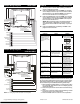
SAMPLE WIRING DIAGRAMS 2
STEP #3 TEST OPERATION 2
TROUBLESHOOTING 2
CALIBRATION 2
This device complies with Part 15 of the FCC rules. Opera-
tion is subject to the following 2 conditions: (1) This device
may not cause harmful interference, and (2) This device
must accept any interference received, including interfer-
ence that may cause undesired operation.
Refer to the chart below, or the wiring diagrams that
follow for thermostat functions and corresponding
thermostat connectors.
*Only used with Heat Pump Systems.
Table of Contents
IMPORTANT:
CAUTION: DISCONNECT POWER TO THE SYS-
TEM BEFORE
INSTALLING THE THERMOSTAT.
STEP #1 PREPARATION
A. Proper installation of the thermostat will be ac-
complished by following these step by step in-
structions. If you are unsure about any of these
steps, call a qualified technician for assistance.
B. Assemble tools:
C. Carefully unpack the thermostat. Save the screws,
bracket, and instructions.
D. Turn off the power to the system at the main fuse
panel. Most systems have a separate breaker for
disconnecting power to the indoor and outdoor
units.
STEP #2 WIRE CONNECTIONS
FUNCTION
INSTALL ON THE
NEW THERMOSTAT
CONNECTOR MARKED
Lo Fan G1
Compressor Y
Heating H2
24 v Power R
Common C
Rev. Valve O*
Hi Fan G2
Remote Sensor +5vdc RS+5
Remote Sensor Signal RS
Remote Sensor Ground RS GND
Dry Contact Switch 1 CK1
Dry Contact Switch 2 CK2
Defrost H1
Flat Blade
Screwdriver
Wire Cutter
and Stripper
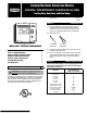
Installation Instructions
DIGITAL THERMOSTAT 53DFS250-SL-BRY
Cooling Only, Heat Cool, and Heat Pump
AUTO
o
o
Am
:
Su
COOL
HEAT
LISTED