INSTALLATION and OPERATING INSTRUCTIONS ROOF MOUNT AIR CONDITIONER Rotary XL (558 Series) and Classic (548 Series) QUICK START MODELS 54812.041 55812.041 54815.041 54815.043 55815.041 SHUR START MODELS 54812.042 55812.042 54815.042 54815.044 55815.042 READ THESE INSTRUCTIONS CAREFULLY, KEEP FOR FUTURE REFERENCE. A V I S : Cet appareil doit etre repare seulement par un reparateur autorise. Modification de I’appareil pourrait etre extremement dangereuse. et pourrait Causer mal ou mort.
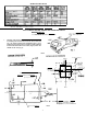
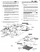
SPECIFICATIONS * For two units USE 5000 watt generator DUO-THERM TESTED UNDER ARI STANDARD 250-74 UL STANDARD 484 . 14” x 14” OPENING FROM ROOF VENT REMOVAL CSA STANDARD 22.2 No. 0,46 and 119 Right 1. Normally, roof mount air conditioners are installed where an existing roof vent has been removed. This creates the 14” x 14” opening required for installation (Fig. 1). If an opening has to be cut, be sure to check for proper clearance on the inside of the RV for the air box (Fig.
INSTALLATION LAYOUT Fig. 4 AIR CONDITIONING UNIT Threaded Hole NOTE: The anchor bolts, supplied as standard equipment, will cover a range of 2 3/8" to 4 1/8" roof thickness. For roof thicknesses, other than the standard, special Bolt Kits can be obtained by special order. For roof sections thinner than the standard, bolts can be cut off, care must be taken so that threads are not damaged. Bolt Kits are available as follows: KIT PART NO.
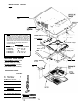
2. Framing is required to provide adequate support and a smooth surface for sealing. Under no circumstances should the roof be constructed to create a low spot where water will accumulate. Any opening between the roof and ceiling should be framed to prevent hot or cold air from being drawn from the cavity. (Be sure to provide opening for electrical supply line.) (See Fig. 4). In the carton you will find the “return air duct”, an aluminum piece of sheet metal folded flat.
8. Control Box Installation: Fasten the control box to the (See ceiling template with two blunt point screws (E). Fig. 6 ). Install one screw (A) in the junction box (part of the control box) which holds it to the ceiling. 9. Connect Power Supply: As mentioned previously, all wiring must comply with the American National Standard Institute, National Electrical Codes and all local codes. NOTE: All required installation hardware is supplied. a. b. C. 10. 11.
12. FOR COOLED AND DEHUMIDIFIED AIR set the thermostat dial to the desired temperature. The warmest setting (WARM) on the dial is approximately 95 degrees; the coolest setting (COLD) is approximately 70 degrees. Place blower selector switch in desired position. High-cool, medium-cool or low-cool positions are used when air conditioning is desired.
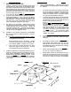
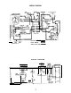
WIRING DIAGRAM COMPRESSOR I FACTORY WIRING I FIELD WIRING GRN WHT BLK 115 V.A.C. 6 0 ~ If SHUR START ONLY CIRCUIT DIAGRAM GRD. FAN CAP Therm.
DUO-THERM, Division of Motor Wheel Corp.
!" ! ( #$% & & ' '