
Heat Pump User Manual


166
APPLICATION DATA (cont)
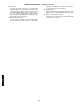
CONDENSER COIL PROTECTION APPLICATIONS
LEGEND
*See “Selection Guide: Environmental Corrosion Protection” Catalog No. 811-217 for more information
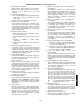
15. ECONOMI$ERIV — The EconoMi$erIV factory-installed
economizer package includes a gear-driven damper system
that modulates the return air and outdoor air supply to the
rooftop unit in order to take advantage of “free cooling” with
outdoor air when conditions are suitable. The system utilizes
industry proven technology available for integrating the use of
outdoor air for cooling with mechanical cooling for 3 through
15-ton rooftop units. The intuitive EconoMi$erIV solid-state
controller optimizes and enhances rooftop operation through
reduced energy consumption, optimal zone comfort, and effi-
cient equipment cycling. This is accomplished by operating
the compressors when the outdoor air temperature is too
warm, integrating the compressors with outdoor air when free
cooling is available, and locking out the compressor when
outdoor air temperature is too cold. The detailed sequence of
operation is described in the controls section with a brief
description of selected application items here.
Thermostat Interface — The EconoMi$erIV control was
designed to work with conventional thermostats that have
Y1 (cooling stage 1), Y2 (cooling stage 2), W1 (heat stage
1), W2 (heat stage 2), and G (fan). In addition, the
EconoMi$erIV will support an occupied/unoccupied switch
(typically integrated into the thermostat or thermidistat).
When the switch is closed, it provides a 24 vac signal to the
unit for occupied mode, and provides no signal to indicate
unoccupied mode. The EconoMi$erIV control can be con-
figured to allow different minimum economizer damper posi-
tions and to allow the use of mechanical cooling in the
occupied mode.
Control Features — The EconoMi$erIV controller provides
superior functionality for rooftop unit operation.
EconoMi$erIV control features are included as follows:
Remote minimum position control
— The EconoMi$erIV
controller can be used with a field-supplied and field-
installed remote minimum position control switch that will
enable and disable the EconoMi$erIV to open or close the
damper beyond the minimum position for modified ventila-
tion, providing 2 to 10 vdc output.
NOTE: Minimum position signal takes priority over the DCV
(Demand and Control Ventilation) maximum position signal.
Demand control ventilation (DCV)
— The EconoMi$erIV
has DCV capability when using an IAQ sensor. This sensor
is typically installed in the return duct or occupied space.
When implementing a DCV control scheme with the
EconoMi$erIV, the control algorithm will modulate the posi-
tion of the damper between two user-configured damper
positions, Maximum DCV Position and Minimum Occupied
position. Design airflow rates for these two damper posi-
tions should be such that when the damper is at the Maxi-
mum DCV position, enough fresh ventilation air will be
brought in to remove contaminants and CO
2
generated by
sources other than people (i.e., since in unoccupied mode).
The Maximum DCV position is intended to satisfy the IAQ
“Base Ventilation Rate.” The Minimum Occupied position
design airflow rate should be sufficient to satisfy ventilation
requirements for removing CO
2
from all sources including
people at the maximum occupancy.
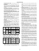
DESCRIPTION
(Enviro-Shield™ Option)
ENVIRONMENT*
Standard, Non-Corrosive Mild Coastal Moderate Coastal Severe Coastal Industrial Combined Coastal and Industrial
Standard, Al/Cu X
Pre-Coated Al/Cu X
Cu/Cu X
E-Coated Al/Cu XX
E-Coated Cu/Cu X
Al/Cu — Aluminum Fin with Copper Tube Coil E-Coated — Extremely Flexible and Durable Epoxy Coating Uniformly
Cu/Cu — Copper Fin with Copper Tube Coil Applied to the Coil Surfaces
Enviro-Shield — Family of Coil Protection Options Pre-Coated — Epoxy Coating Applied to Fin Stock Material
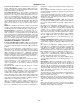
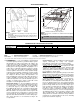
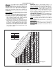
Concentric Duct Distribution — 542J150,180
Concentric Duct Details — 542J150,180
NOTES:
1. Do not drill in this area, damage to basepan may result in
water leak.
2. A 90-degree elbow must be provided in the supply ductwork
to comply with UL (Underwriters Laboratories) codes for use
with electric heat.
6'-2 3/8'' MAX.
5'-9 3/16'' MAX.
5 3/16''
B
A
BAFFLE
A
B
24'' MIN.
1'-0 3/16''
1'-7 15/16''
4'-6 13/16''
1'-0 3/16''
1'-10 11/16''
MAX.
Shaded area indicates block-off panels.
NOTE: Dimensions A, A′ and B, B′ are obtained from field-supplied
ceiling diffuser.
CAUTION: Concentric ducts may only be installed on units
without electric heat. Personal injury or unit damage may result.
a50-6549
a50-530