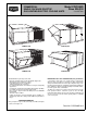
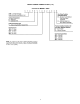
COMMERCIAL Model 579F/580D SINGLE PACKAGE ROOFTOP Sizes 036-300 GAS HEATING/ELECTRIC COOLING UNITS 3 to 25 Tons 580D036-072 579F180,216 580D090-150 579F240,300 Standard-Efficiency Rooftop Units with: • Exclusive integrated gas control board with diagnostics • Alumagard™ heat exchanger coating • Induced-draft fan for gas combustion • Tubular, dimpled heat exchangers • Pre-painted galvanized steel cabinet for long life and quality appearance • Commercial strength baserails with built-in rigging capabilit
DURABLE, DEPENDABLE CONSTRUCTION— Designed for durability in any climate, the weather-resistant cabinets are constructed of galvanized steel and bonderized, and all exterior panels are coated with a prepainted baked enamel finish. The paint finish is non-chalking, and is capable of withstanding ASTM B117 500-hour Salt Spray Test. All internal cabinet panels are primed, permitting longer life and a more attractive appearance for the entire unit.
blade design with standard enthalpy controls. In addition, the Parablade economizer has a spring return built into the damper motor to provide reliable close-on-power-loss. The Parablade economizer comes equipped with up to 45% barometric relief capability for high outdoor airflow applications. For units without economizer, year-round ventilation is enhanced by a manual outdoor-air damper (ordered as standard on 579F180-300; ordered as an accessory or an option on 580D036-150 units).
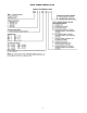
MODEL NUMBER NOMENCLATURE 580D036-150 MODELS ONLY *Contains high pressure, (loss-of-charge) low-pressure, and freeze protection cutout switches. NOTE: The example model number 580DEV090180CB designates a 71⁄2 ton 460-3-60 volt gas/electric rooftop unit with 180,000 Btuh natural gas heat, Durablade economizer, and alternate drive.
MODEL NUMBER NOMENCLATURE (cont) 579F180-300 MODELS ONLY NOTE: The example model number 579FEV180230CB designates a 15-ton 460-3-60 volt gas/electric rooftop unit with 230,000 Btuh natural gas heat input, economizer, and the standard low-medium fan drive static capability.
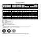
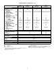
ARI* CAPACITY RATINGS UNIT 580D NOMINAL TONS STANDARD CFM 036 048 060 3 4 5 1200 1600 2000 UNIT NOMINAL TONS STANDARD CFM 580D072 580D090 580D102 580D120 580D150 579F180 579F216 579F240 579F300 6 71⁄2 81⁄2 10 121⁄2 15 18 20 25 2100 2800 3000 4000 4500 5250 6000 6200 7200 Bels db EER IPLV SEER wb — — — — — — NET COOLING CAPACITY (Btuh) 35,000 47,000 57,000 NET COOLING CAPACITY (Btuh) 72,000 85,000 99,000 117,000 145,000 178,000 190,000 222,000 268,000 SEER† TOTAL kW Belt Drive Direct Driv
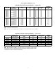
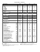
ARI* CAPACITY RATINGS (cont) HEATING CAPACITIES AND EFFICIENCIES — 580D036-150 UNIT 580D 036 036 048 048 048 060 060 060 072 072 072 090 090 090 102 102 102 120 120 120 150 150 074 115 074 115 150 074 115 150 074 115 150 125 180 224 125 184 224 180 224 250 224 250 HEATING INPUT (Btuh) Stage 2/Stage 1 OUTPUT CAPACITY (Btuh) TEMPERATURE RISE (F) AFUE (%) STEADY-STATE EFFICIENCY (%) —/ 72,000 115,000/ 82,000 —/ 72,000 —/115,000 150,000/120,000 —/ 72,000 —/115,000 150,000/120,000 —/ 72,000 —/115,000 150,
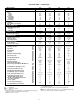
PHYSICAL DATA — 580D036-072 UNIT SIZE 580D NOMINAL CAPACITY (tons) OPERATING WEIGHT (lb) Unit Al/Al* Al/Cu* Cu/Cu* Economizer Durablade Parablade Roof Curb† COMPRESSOR Quantity No. Cylinders (per Circuit) Oil (oz) REFRIGERANT TYPE Expansion Device Operating Charge (lb-oz) Circuit 1 Circuit 2 CONDENSER COIL Rows...Fins/in. Total Face Area (sq ft) CONDENSER FAN Nominal Cfm Quantity...Diameter (in.) Motor Hp...Rpm Watts Input (Total) EVAPORATOR COIL Rows...Fins/in.
PHYSICAL DATA — 580D036-072 (cont) UNIT SIZE 580D FURNACE SECTION Rollout Switch Cutout Temp (F)** Burner Orifice Diameter (in. ...drill size) Natural Gas Std Liquid Propane Alt Pilot Orifice Diameter (Quantity) in. ...drill size Natural Gas Std Liquid Propane Alt Thermostat Heat Anticipator Setting (amps) 208/230 v and 575 v Stage 1 Stage 2 460 v Stage 1 Stage 2 Gas Input (Btuh) Stage 1 Stage 2 Efficiency (Steady State) (%) Temperature Rise Range Manifold Pressure (in.
PHYSICAL DATA — 580D090-150 UNIT SIZE 580D NOMINAL CAPACITY (tons) OPERATING WEIGHT (lb) Unit Al/Al* Al/Cu* Cu/Cu* Economizer Durablade Parablade Roof Curb† COMPRESSOR Quantity No. Cylinders (per Circuit) Oil (oz) REFRIGERANT TYPE Expansion Device Operating Charge (lb-oz) Circuit 1 Circuit 2 CONDENSER COIL Rows...Fins/in. Total Face Area (sq ft) CONDENSER FAN Nominal Cfm Quantity...Diameter (in.) Motor Hp...Rpm Watts Input (Total) EVAPORATOR COIL Rows...Fins/in.
PHYSICAL DATA — 580D090-150 (cont) UNIT SIZE 580D FURNACE SECTION Rollout Switch Cutout Temp (F)†† Burner Orifice Diameter (in. ...drill size) Natural Gas Std Liquid Propane Alt Pilot Orifice Diameter (Quantity) in. ...drill size Natural Gas Std Liquid Propane Alt Thermostat Heat Anticipator Setting (amps) 208/230 v and 575 v Stage 1 Stage 2 460 v Stage 1 Stage 2 Gas Input (Btuh) Stage 1 Stage 2 Efficiency (Steady State) (%) Temperature Rise Range Manifold Pressure (in.
PHYSICAL DATA — 579F180-300 UNIT SIZE 579F NOMINAL CAPACITY (tons) OPERATING WEIGHT (lb) Unit Al/Al* Economizer Roof Curb† COMPRESSOR Model No. ...Quantity (Number of Cylinders) Oil (oz) No. of Cylinders (per circuit) Cooling Capacity Stages (%) REFRIGERANT TYPE Expansion Device Operating Charge (lb-oz) Circuit 1** Circuit 2 CONDENSER COIL Rows...Fins/in. Total Face Area (sq ft) CONDENSER FAN Nominal Cfm Quantity...Diameter (in.) Motor Hp...Rpm Watts Input (Total) EVAPORATOR COIL Rows...Fins/in.
PHYSICAL DATA — 579F180-300 (cont) UNIT SIZE 579F 180 LOW/HIGH HEAT 216 LOW/HIGH HEAT 240 LOW/HIGH HEAT 300 LOW/HIGH HEAT FURNACE SECTION Rollout Switch Cutout Temp (F)†† 190 190 190 190 Burner Orifice Diameter (in. ...drill size) Natural Gas 0.1405...28/0.136...29 0.1405...28/0.136...29 0.1405...28/0.136...29 0.1405...28/0.136...29 Thermostat Heat Anticipator Setting (amps) 208/230 v Stage 1 0.98 0.98 0.98 0.98 Stage 2 0.44 0.44 0.44 0.44 460 v Stage 1 0.80 0.80 0.80 0.80 Stage 2 0.44 0.44 0.44 0.
OPTIONS AND ACCESSORIES ITEM Parablade Economizer (036-150 only) Parablade Economizer with Power Exhaust (036-150) Integrated Economizer (180-300) Durablade Integrated Economizer (036-150; Includes Hood) Manual Outdoor-Air Damper (ordered as standard on 180-300 units without optional economizer) Controls Upgrade Kit (036-150)** Condenser Coil Grille (036-150) Alternate Drive (090, 180-300) Alternate Motor and Drive (036-060, 120,150) LP (Liquid Propane) Conversion Kit Commercial Programmable Thermostat 25%
OPTIONS AND ACCESSORIES (cont) LIQUID PROPANE (LP) CONVERSION KITS BRYANT COMMERCIAL PROGRAMMABLE THERMOSTAT Designed specifically for use with Bryant commercial systems, this Bryant programmable thermostat features LED occupied/unoccupied displays and setback mode which can override continuous fan operation.
OPTIONS AND ACCESSORIES (cont) ACCUSENSOR™ II CONTROL (036-150 Only) POWER EXHAUST (180-300 SHOWN) ACCUSENSOR III SENSOR C SO D TR REV. B 1 9 8 8 1 8 A B S 1 P T MINIMUM 3 POSITION OPEN 5 4 2 P1 T1 TR C 24VAC 2 TR1 1 3 mA MIN. AT 11 VDC B A ENTHALPY CONTROL 3 D CW–SETPOINTS–CCW RUSH AT 24VAC CONTACTS SHOWN IN HIGH ENTHALPY OR UNPOWERED STATE °F CONTACT RATINGS: 1.5A RUN, 3.5A IN OUTDOOR TEMP.
BASE UNIT DIMENSIONS — 580D036-072 UNIT 580D 036 048 060 072 A lb 140 142 150 165 kg 63.5 64.4 68.0 74.8 lb 105 106 115 136 CORNER WEIGHT* B C kg lb 47.6 159 48.1 162 52.2 160 61.7 200 D kg 72.1 73.5 72.6 90.7 lb 56 60 65 64 kg 25.4 27.2 29.5 29.0 *Weights are for unit only (aluminum plate fins) and do not include options or crating. A B C CONNECTION SIZES 11⁄169 Dia.
BASE UNIT DIMENSIONS — 580D090-150 UNIT 580D 090 102 120 150 A lb 189 191 225 228 kg 86 87 102 103 CORNER B lb kg 161 73 163 74 192 87 195 88 WEIGHT* C lb kg 239 109 242 110 285 129 289 131 D lb 280 284 333 338 kg 127 129 151 153 ‘‘H’’ ft-in. mm 378 1-27⁄8 3-37⁄8 1013 759 2-57⁄8 1-27⁄8 378 DIMENSIONS ‘‘J’’ ‘‘K’’ ft-in. mm ft-in. 3-55⁄16 1050 2-911⁄16 3-55⁄16 1050 2-911⁄16 4-15⁄16 1253 3-03⁄8 4-15⁄16 1253 3-03⁄8 mm 856 856 924 924 ‘‘L’’ ft-in.
BASE UNIT DIMENSIONS — 579F180,216 UNIT 579F 180 216 UNIT 579F 180 216 ft-in. 1-10 1- 8 CORNER WEIGHT* B C Lb kg lb kg 370 168 358 162 508 230 486 220 lb 538 636 ft-in. 3-2 3-7 A lb 384 520 DIMENSIONS Y mm ft-in. mm 965 4-0 1219 1090 3-2 965 X kg 174 235 Z mm 559 508 D kg 244 288 *Weights are for unit only (aluminum plate fins) and do not include options or crating. NOTES: 1. Dimensions in ( 2. 3. ) are in millimeters. Center of gravity. Direction of airflow. 4.
BASE UNIT DIMENSIONS — 579F240,300 NOTES: 1. Dimensions in ( 2. ) are in millimeters. Center of gravity. 3. Direction of airflow. 4. Ductwork to be attached to accessory roof curb or adapter only. 5. Minimum clearance: a. Rear: 7809 (2134) for coil removal. This dimension can be reduced to 4809 (1219) if conditions permit coil removal from the top. b. 4809 (1219) to combustible surfaces, all four sides (includes between units). c. Left side: 4809 (1219) for proper condenser coil airflow. d.
ACCESSORY DIMENSIONS ROOF CURB ACCESSORY CRRFCURB001A00 CRRFCURB002A00 ‘‘A’’ UNIT SIZE 580D 18-29 [356] 28-09 [610] 036-072 UNIT SIZE 580D ‘‘B’’ ‘‘C’’ ‘‘D’’ ALT DRAIN HOLE 036-072 18-911⁄169 [551] 18-49 [406] 13⁄49 [45] ‘‘E’’ GAS POWER ⁄ 9 NPT 34 ⁄ 9 NPT 34 ⁄ 9 NPT 34 11⁄49 NPT CONTROL CONNECTOR PKG ACY ⁄ 9 NPT CRBTMPWR001A00* (Thru-The-Bottom) CRBTMPWR002A00* (Thru-The-Bottom) 12 ⁄ 9 NPT 12 *Either connector package available for either roof curb. NOTES: 1.
ACCESSORY DIMENSIONS (cont) ROOF CURB ACCESSORY ‘‘A’’ UNIT SIZE 580D CRRFCURB003A00 18-29 [356] 28-09 [610] 090150 CRRFCURB004A00 UNIT SIZE 580D ‘‘B’’ ‘‘C’’ ‘‘D’’ ALT DRAIN HOLE ‘‘E’’ GAS ⁄ 9 NPT ⁄ 9NPT 12 ⁄ 9 NPT 11⁄49 NPT 12 34 090- 28-87⁄169 18-1015⁄169 150 [827] [583] 13⁄49 [45] POWER CONTROL 34 34 ⁄ 9 NPT ⁄ 9 NPT CONNECTOR PACKAGE ACCESSORY CRBTMPWR001A00* (THRU-THE-BOTTOM CONNECTIONS) CRBTMPWR002A00* (THRU-THE-BOTTOM CONNECTIONS) *Either connector package available for either r
ACCESSORY DIMENSIONS (cont) NOTES: 1. Roof curb accessory is shipped unassembled. 2. Insulated panels, 19 thick neoprene coated, 11⁄2 lb density. 3. Dimensions in ( ) are in millimeters. 4. Direction of airflow. NOTE: To prevent the hazard of stagnant water build-up in the drain pan of the indoor section, unit can only be pitched as shown. 5. Roof curb: 16 ga. (VA03-56) steel. PKG. NO. REF. 308450-201 CURB HEIGHT 18-29 (355) 308450-202 28-09 (610) 308450-203 28-09 (610) LEGEND COMPR SECT.
ACCESSORY DIMENSIONS (cont) NOTE: 389210-201 is a fully factory preassembled horizontal adapter and includes an insulated high static regain transition duct which substantially improves fan static performance. The Barometric Relief Damper and Power Exhaust accessories are not available with the horizontal adapter. ACCESSORY PACKAGE NO.
SELECTION PROCEDURE (with 579F180 example) IV DETERMINE FAN SPEED AND POWER REQUIREMENTS AT DESIGN CONDITIONS. Before entering the Fan Performance tables, calculate the total static pressure required based on unit components. From the given and the Accessory/FIOP Static Pressure table on page 52 find: External static pressure 0.60 in. wg Economizer static pressure 0.04 in. wg Total static pressure 0.64 in. wg I DETERMINE COOLING AND HEATING REQUIREMENTS AT DESIGN CONDITIONS.
PERFORMANCE DATA COOLING CAPACITIES 580D036 (3 TONS) 580D060 (5 TONS) Air Entering Evaporator — Cfm/BF Temp (F) 900/0.11 1200/0.14 1500/0.17 Air Entering Condenser Air Entering Evaporator — Ewb (F) (Edb) 72 67 62 72 67 62 72 67 62 TC 42.8 38.9 35.0 44.8 40.8 37.0 45.8 41.9 38.2 75 SHC 20.0 24.5 28.7 21.8 27.5 32.8 23.0 30.0 36.0 kW 2.91 2.81 2.70 2.99 2.88 2.78 3.02 2.92 2.82 TC 40.8 36.9 33.3 42.5 38.7 35.0 43.6 39.9 36.1 85 SHC 19.4 23.7 27.9 21.0 26.8 31.8 22.6 29.7 35.1 kW 3.14 3.01 2.90 3.20 3.08 2.
PERFORMANCE DATA (cont) COOLING CAPACITIES (cont) 580D090 (71⁄2 TONS) Temp (F) Air Entering Condenser (Edb) 75 85 95 105 115 TC SHC kW TC SHC kW TC SHC kW TC SHC kW TC SHC kW 2250/0.07 72 102.8 49.4 7.14 98.2 48.0 7.66 93.8 46.4 8.18 88.4 44.6 8.68 82.8 42.6 9.16 67 94.8 61.8 6.82 90.2 60.2 7.34 85.2 58.2 7.84 79.8 56.2 8.30 73.8 53.8 8.78 62 86.2 73.2 6.50 81.6 71.2 7.00 76.6 68.8 7.48 70.8 66.0 7.98 66.0 63.2 8.42 Air Entering Evaporator — Cfm/BF 2800/0.09 3000/0.10 3750/0.
PERFORMANCE DATA (cont) COOLING CAPACITIES (cont) 580D120 (10 TONS) Temp (F) Air Entering Condenser (Edb) TC SHC kW TC SHC kW TC SHC kW TC SHC kW TC SHC kW 75 85 95 105 115 3000/0.095 72 135.8 66.8 9.76 130.0 64.3 10.41 124.1 62.2 11.13 118.1 60.4 11.93 115.0 59.4 12.26 67 124.8 82.6 9.41 119.6 80.5 10.07 113.7 78.4 10.78 104.6 74.9 11.52 98.0 72.4 11.82 Air Entering Evaporator — Cfm/BF 4000/0.125 5000/0.15 Air Entering Evaporator — Ewb (F) 62 72 67 62 72 67 62 112.0 142.4 130.6 119.8 146.5 134.2 123.
PERFORMANCE DATA (cont) COOLING CAPACITIES (cont) 579F180 (15 TONS) Temp (F) Air Entering Condenser (Edb) 75 85 95 105 115 TC SHC kW TC SHC kW TC SHC kW TC SHC kW TC SHC kW 4500/0.08 72 212.0 101.0 15.20 205.0 98.5 16.60 197.0 95.8 18.00 190.0 93.3 19.40 180.0 90.0 20.80 67 195.0 126.0 14.70 188.0 123.0 16.10 180.0 120.0 17.40 172.0 117.0 18.70 161.0 112.0 19.90 5250/0.10 62 179.0 148.0 14.20 171.0 145.0 15.50 162.0 141.0 16.70 152.0 136.0 17.90 142.0 131.0 19.10 72 216.0 105.0 15.40 210.0 103.0 16.
PERFORMANCE DATA (cont) COOLING CAPACITIES (cont) 579F240 (20 TONS) Temp (F) Air Entering Condenser (Edb) 75 85 95 105 115 125 TC SHC kW TC SHC kW TC SHC kW TC SHC kW TC SHC kW TC SHC kW 6000/0.06 72 274.0 130.4 16.92 264.0 127.6 18.54 252.0 124.4 20.20 240.0 120.0 21.80 228.0 116.0 23.40 214.0 111.0 24.80 67 250.0 163.6 16.40 240.0 159.8 18.00 228.0 155.4 19.52 216.0 150.8 21.00 204.0 146.2 22.40 188.8 140.8 23.80 7000/0.07 62 226.0 194.4 15.90 216.0 189.8 17.36 204.0 184.6 18.82 190.6 178.4 20.20 176.
PERFORMANCE DATA (cont) FAN PERFORMANCE — 580D036-150 VERTICAL DISCHARGE UNITS 580D036 (3 TONS) — STANDARD MOTOR (DIRECT DRIVE) Low Speed Airflow 208 V 230, 460, 575 V (Cfm) Esp Bhp Watts Esp Bhp Watts 900 1000 1100 1200 1300 1400 1500 0.49 0.42 0.37 0.33 0.27 0.20 0.16 0.21 0.23 0.24 0.26 0.27 0.29 0.30 253 270 287 304 321 338 355 0.50 0.43 0.38 0.33 0.28 0.23 0.18 0.23 0.25 0.26 0.27 0.29 0.30 0.
PERFORMANCE DATA (cont) FAN PERFORMANCE — 580D036-150 VERTICAL DISCHARGE UNITS (cont) 580D048 (4 TONS) — STANDARD MOTOR (DIRECT DRIVE) Low Speed Airflow 208 V 230, 460, 575 V (Cfm) Esp Bhp Watts Esp Bhp Watts 1200 1300 1400 1500 1600 1700 1800 1900 2000 0.68 0.61 0.53 0.45 0.36 0.26 0.15 0.04 — 0.41 0.42 0.45 0.47 0.49 0.52 0.54 0.56 — 458 471 503 536 557 584 610 629 — 0.74 0.67 0.59 0.51 0.42 0.32 0.22 0.11 — 0.45 0.46 0.49 0.52 0.54 0.57 0.60 0.
PERFORMANCE DATA (cont) FAN PERFORMANCE — 580D036-150 VERTICAL DISCHARGE UNITS (cont) 580D060 (5 TONS) — STANDARD MOTOR (DIRECT DRIVE) Low Speed Medium Speed Airflow 208 V 230, 460, 575 V 208 V 230, 460, 575 V (Cfm) Esp Bhp Watts Esp Bhp Watts Esp Bhp Watts Esp Bhp Watts 1500 1600 1700 1800 1900 2000 2100 2200 2300 2400 2500 0.69 0.49 0.29 0.09 — — — — — — — 0.67 0.70 0.73 0.75 — — — — — — — 750 780 810 839 — — — — — — — 1.01 0.85 0.70 0.54 0.39 0.23 0.08 — — — — 0.71 0.74 0.77 0.80 0.83 0.86 0.
PERFORMANCE DATA (cont) FAN PERFORMANCE — 580D036-150 VERTICAL DISCHARGE UNITS (cont) 580D072 (6 TONS)* External Static Pressure (in. wg) Airflow (Cfm) Rpm 0.2 Bhp Watts Rpm 0.4 Bhp Watts Rpm 0.6 Bhp Watts Rpm 0.8 Bhp Watts Rpm 1.0 Bhp Watts 978 1023 1068 1115 1159 1202 1237 1272 1320 1361 1402 1446 1489 0.66 0.78 0.90 1.00 1.15 1.29 1.41 1.53 1.68 1.82 1.95 2.16 2.
PERFORMANCE DATA (cont) FAN PERFORMANCE — 580D036-150 VERTICAL DISCHARGE UNITS (cont) 580D090 (71⁄2 TONS)* External Static Pressure (in. wg) Airflow (Cfm) 2250 2300 2400 2500 2550 2600 2700 2800 2900 3000 3100 3200 3300 3400 3500 3600 3700 3750 Rpm 0.2 Bhp Rpm 0.4 Bhp Watts Watts Rpm 0.6 Bhp Watts Rpm 0.8 Bhp Watts Rpm 1.0 Bhp 514 521 536 551 559 567 582 598 614 630 646 662 679 695 712 729 745 754 0.55 0.57 0.63 0.69 0.72 0.75 0.83 0.90 0.98 1.07 1.16 1.26 1.36 1.47 1.59 1.71 1.84 1.
PERFORMANCE DATA (cont) FAN PERFORMANCE — 580D036-150 VERTICAL DISCHARGE UNITS (cont) 580D102 (81⁄2 TONS)* External Static Pressure (in. wg) Airflow (Cfm) 2550 2600 2700 2800 2900 3000 3100 3200 3300 3400 3500 3600 3700 3750 3800 3900 4000 4100 4200 4250 Rpm 0.2 Bhp Rpm 0.4 Bhp Watts Watts Rpm 0.6 Bhp Watts Rpm 0.8 Bhp Watts Rpm 1.0 Bhp 559 567 582 598 614 630 646 662 679 695 712 729 745 754 762 779 796 813 830 839 0.72 0.75 0.83 0.90 0.98 1.07 1.16 1.26 1.36 1.47 1.59 1.71 1.84 1.91 1.98 2.
PERFORMANCE DATA (cont) FAN PERFORMANCE — 580D036-150 VERTICAL DISCHARGE UNITS (cont) 580D120 (10 TONS)* External Static Pressure (in. wg) Airflow (Cfm) 3000 3100 3200 3300 3400 3500 3600 3700 3800 3900 4000 4100 4200 4300 4400 4500 4600 4700 4800 4900 5000 Rpm 0.2 Bhp Watts 592 607 622 638 653 669 684 700 715 731 747 763 778 794 810 826 842 858 874 890 906 0.76 0.83 0.90 0.98 1.06 1.15 1.24 1.33 1.43 1.54 1.64 1.76 1.88 2.00 2.13 2.27 2.41 2.55 2.70 2.86 3.
PERFORMANCE DATA (cont) FAN PERFORMANCE — 580D036-150 VERTICAL DISCHARGE UNITS (cont) 580D150 (121⁄2 TONS)* External Static Pressure (in. wg) Airflow (Cfm) 3750 3800 3900 4000 4100 4200 4300 4400 4500 4600 4700 4800 4900 5000 5100 5200 5300 5400 5500 5600 5700 5800 5900 6000 6100 6250 Rpm 0.2 Bhp Watts 737 745 761 777 793 810 826 842 859 876 892 909 926 942 959 976 993 1010 1027 1043 1060 1077 1094 1111 — — 1.41 1.46 1.56 1.67 1.79 1.91 2.04 2.17 2.31 2.45 2.60 2.77 2.93 3.11 3.29 3.47 3.67 3.87 4.
PERFORMANCE DATA (cont) FAN PERFORMANCE — 580D036-150 HORIZONTAL DISCHARGE UNITS 580D036 (3 TONS) — STANDARD MOTOR (DIRECT DRIVE) Low Speed Airflow 208 v 230, 460, 575 v (Cfm) Esp Bhp Watts Esp Bhp Watts 900 1000 1100 1200 1300 1400 1500 0.54 0.49 0.43 0.39 0.33 0.26 0.21 0.21 0.23 0.24 0.26 0.27 0.29 0.30 253 270 287 304 321 338 355 0.57 0.51 0.45 0.40 0.35 0.28 0.23 0.23 0.25 0.26 0.27 0.29 0.30 0.
PERFORMANCE DATA (cont) FAN PERFORMANCE — 580D036-150 HORIZONTAL DISCHARGE UNITS (cont) 580D048 (4 TONS) — STANDARD MOTOR (DIRECT DRIVE) Low Speed Airflow 208 v 230, 460, 575 v (Cfm) Esp Bhp Watts Esp Bhp Watts 1200 1300 1400 1500 1600 1700 1800 1900 2000 0.75 0.68 0.60 0.51 0.42 0.32 0.21 0.09 — 0.41 0.42 0.45 0.47 0.49 0.52 0.54 0.56 — 458 471 503 536 557 584 610 629 — 0.81 0.74 0.66 0.58 0.49 0.39 0.29 0.18 0.06 0.45 0.46 0.49 0.52 0.54 0.57 0.60 0.62 0.
PERFORMANCE DATA (cont) FAN PERFORMANCE — 580D036-150 HORIZONTAL DISCHARGE UNITS (cont) 580D060 (5 TONS) — STANDARD MOTOR (DIRECT DRIVE) Low Speed Medium Speed Airflow 208 V 230, 460, 575 V 208 V 230,460, 575 V (Cfm) Esp Bhp Watts Esp Bhp Watts Esp Bhp Watts Esp Bhp Watts 1500 1600 1700 1800 1900 2000 2100 2200 2300 2400 2500 0.74 0.54 0.34 0.14 — — — — — — — 0.67 0.70 0.73 0.75 — — — — — — — 750 780 810 839 — — — — — — — 1.06 0.90 0.75 0.59 0.44 0.28 0.13 — — — — 0.71 0.74 0.77 0.80 0.83 0.86 0.
PERFORMANCE DATA (cont) FAN PERFORMANCE — 580D036-150 HORIZONTAL DISCHARGE UNITS (cont) 580D072 (6 TONS)* External Static Pressure (in. wg) Airflow (Cfm) Rpm 0.2 Bhp Watts Rpm 0.4 Bhp Watts Rpm 0.6 Bhp Watts Rpm 0.8 Bhp Watts Rpm 1.0 Bhp Watts 942 982 1022 1063 1104 1130 1174 1201 1246 1285 1304 1345 1378 0.73 0.83 0.94 1.10 1.20 1.27 1.37 1.50 1.67 1.80 1.85 2.05 2.
PERFORMANCE DATA (cont) FAN PERFORMANCE — 580D036-150 HORIZONTAL DISCHARGE UNITS (cont) 580D090 (71⁄2 TONS)* External Static Pressure (in. wg) Airflow (Cfm) Rpm 0.4 Bhp Watts Rpm 0.6 Bhp Watts Rpm 0.8 Bhp Watts Rpm 0.9 Bhp Watts Rpm 1.0 Bhp Watts 586 592 606 619 627 634 648 662 676 690 704 718 732 747 762 777 792 800 0.73 0.76 0.83 0.90 0.94 0.97 1.05 1.13 1.21 1.30 1.39 1.49 1.59 1.70 1.82 1.94 2.07 2.
PERFORMANCE DATA (cont) FAN PERFORMANCE — 580D036-150 HORIZONTAL DISCHARGE UNITS (cont) 580D102 (81⁄2 TONS)* External Static Pressure (in. wg) Airflow (Cfm) Rpm 0.4 Bhp Watts Rpm 0.6 Bhp Watts Rpm 0.8 Bhp Watts Rpm 0.9 Bhp Watts Rpm 1.0 Bhp Watts 627 634 648 662 676 690 704 718 732 747 762 777 792 800 807 822 838 854 869 877 0.94 0.97 1.05 1.13 1.21 1.30 1.39 1.49 1.59 1.70 1.82 1.94 2.07 2.14 2.21 2.35 2.50 2.66 2.82 2.
PERFORMANCE DATA (cont) FAN PERFORMANCE — 580D036-150 HORIZONTAL DISCHARGE UNITS (cont) 580D120 (10 TONS)* External Static Pressure (in. wg) Airflow (Cfm) 3000 3100 3200 3300 3400 3500 3600 3700 3800 3900 4000 4100 4200 4300 4400 4500 4600 4700 4800 4900 5000 Rpm 0.2 Bhp Watts 552 565 578 591 605 619 633 648 662 677 692 707 722 737 752 768 783 799 814 — — 0.68 0.74 0.81 0.88 0.96 1.04 1.13 1.23 1.33 1.44 1.55 1.67 1.80 1.94 2.08 2.24 2.40 2.56 2.
PERFORMANCE DATA (cont) FAN PERFORMANCE — 580D036-150 HORIZONTAL DISCHARGE UNITS (cont) 580D150 (121⁄2 TONS)* External Static Pressure (in. wg) Airflow (Cfm) 3750 3800 3900 4000 4100 4200 4300 4400 4500 4600 4700 4800 4900 5000 5100 5200 5300 5400 5500 5600 5700 5800 5900 6000 6100 6250 Rpm 0.2 Bhp Watts 684 691 705 720 734 749 764 779 793 808 822 837 852 867 882 896 911 926 940 955 970 985 1000 1015 1030 1062 1.24 1.28 1.37 1.47 1.56 1.66 1.77 1.88 1.99 2.11 2.24 2.37 2.51 2.65 2.79 2.95 3.11 3.27 3.
PERFORMANCE DATA (cont) FAN PERFORMANCE — 579F180-300 UNITS 579F180 (15 TONS) External Static Pressure (in. wg) Airflow (Cfm) 4500 4800 5100 5400 5700 6000 6300 6600 6900 7200 7500 Rpm 0.2 Bhp Watts 801 843 885 927 971 1016 1059 1104 1150 1194 1238 1.05 1.25 1.47 1.71 1.98 2.28 2.60 2.96 3.35 3.77 4.23 933 1110 1306 1519 1758 2025 2309 2629 2975 3348 3758 Rpm 0.4 Bhp Watts Rpm 0.6 Bhp Watts Rpm 0.8 Bhp Watts Rpm 1.0 Bhp Watts Rpm 1.
PERFORMANCE DATA (cont) FAN PERFORMANCE — 579F180-300 UNITS (cont) 579F216 (18 TONS)* External Static Pressure (in. wg) Airflow (Cfm) 5000 5500 6000 6500 7000 7200 7500 8000 8500 9000 Rpm 0.2 Bhp Watts 669 717 767 817 869 889 920 973 1026 1079 1.10 1.40 1.80 2.20 2.70 2.94 3.30 3.90 4.60 5.40 1019 1292 1617 1992 2427 2624 2919 3476 4102 4800 Rpm 0.4 Bhp Watts Rpm 0.6 Bhp Watts Rpm 0.8 Bhp Watts Rpm 1.0 Bhp Watts Rpm 1.2 Bhp Watts 772 813 858 903 950 969 998 1047 1097 — 1.40 1.80 2.
PERFORMANCE DATA (cont) FAN PERFORMANCE — 579F180-300 UNITS (cont) 579F240 (20 TONS)* External Static Pressure (in. wg) Airflow (Cfm) 6000 6500 7000 7500 8000 8500 9000 9500 10,000 Rpm 0.2 Bhp Watts 767 817 869 920 973 1026 1079 1133 1188 1.80 2.20 2.70 3.30 3.90 4.60 5.40 6.20 7.20 1617 1992 2427 2919 3476 4102 4800 5576 6432 Rpm 0.4 Bhp Watts Rpm 0.6 Bhp Watts Rpm 0.8 Bhp Watts Rpm 1.0 Bhp Watts Rpm 1.2 Bhp Watts 858 903 950 998 1047 1097 1147 1199 1250 2.20 2.60 3.10 3.70 4.30 5.
PERFORMANCE DATA (cont) FAN PERFORMANCE — 579F180-300 UNITS (cont) 579F300 (25 TONS)* External Static Pressure (in. wg) Airflow (Cfm) Rpm 7,500 8,000 8,500 9,000 9,500 10,000 10,500 11,000 11,250 0.2 Bhp 962 3.39 1017 4.04 1072 4.76 1128 5.57 1185 6.47 1241 7.45 1298 8.54 1355 9.72 1384 10.36 Watts Rpm 3123 3717 4385 5129 5955 6865 7865 8956 9540 0.4 Bhp Watts 1039 3.81 3507 1091 4.48 4126 1143 5.23 4818 1196 6.07 5587 1250 6.99 6437 1304 8.00 7372 1359 9.12 8396 1414 10.33 9512 1441 10.
PERFORMANCE DATA (cont) 579F180-300 HORIZONTAL SUPPLY/RETURN FAN PERFORMANCE WITH 389210-201 HIGH STATIC REGAIN ADAPTER CURB NOTES: 1. Dimensions are in millimeters. 2. The 389210-201 high static regain adapter accessories may be used to provide horizontal supply/return. NOTE: The 389210-201 horizontal supply/return adapter accessories improve 579F180-300 fan performance by increasing external static pressure by amount shown above.
PERFORMANCE DATA (cont) ACCESSORY/FIOP STATIC PRESSURE* (in. wg) − 580D036-072 CFM COMPONENT 900 0.05 0.08 Durablade Economizer Parablade Economizer 1200 0.05 0.10 1400 0.05 0.17 1600 0.05 0.26 1800 0.05 0.33 2000 0.05 0.34 2200 0.05 0.36 2400 0.05 0.40 2600 0.05 0.44 3000 0.05 — LEGEND FIOP − Factory-Installed Option *The static pressure must be added to external static pressure.
PERFORMANCE DATA (cont) Durablade Economizer Barometric Relief Damper Characteristics — 580D036-150 Parablade Economizer Barometric Relief Damper Characteristics — 580D090-150 ALTITUDE COMPENSATION* — 580D036-072 ELEVATION (ft) 0-2,000 2,000 3,000 4,000 5,000 6,000 7,000 8,000 9,000 10,000 11,000 12,000 13,000 14,000 72,000 AND 115,000 BTUH NOMINAL INPUT Natural Liquid Gas Propane Orifice Orifice Size† Size† 33 43 34 43 35 44 36 44 36 44 37 45 37 45 38 46 39 47 41 48 43 48 44 49 44 49 45 50 150,000 BT
PERFORMANCE DATA (cont) ALTITUDE COMPENSATION* — 580D090-150 ALTITUDE COMPENSATION* — 579F180-300 125,000, 180,000, 250,000 BTUH AND 224,000 BTUH NOMINAL INPUT NOMINAL INPUT ELEVATION Natural Liquid Natural Liquid (ft) Gas Propane Gas Propane Orifice Orifice Orifice Orifice Size† Size† Size† Size† 0-2,000 31 41 30 38 2,000 32 42 30 39 3,000 32 42 31 40 4,000 32 42 32 41 5,000 33 43 33 42 6,000 34 43 34 43 7,000 35 44 35 43 8,000 36 44 36 44 9,000 37 45 37 44 10,000 38 46 38 45 11,000 39 47 39 45 12,000 40
PERFORMANCE DATA (cont) EVAPORATOR-FAN MOTOR PERFORMANCE UNIT EVAPORATOR-FAN MOTOR Standard 580D036 Alternate Standard 580D048 Alternate Standard 580D060 Alternate 580D072 Standard 580D090 Standard 580D102 Standard Standard 580D120 Alternate Standard 580D150 Alternate 579F180 Standard 579F216 Standard 579F240 Standard 579F300 Standard UNIT VOLTAGE 208/230 460 575 208/230 460 575 208/230 460 575 208/230 460 575 208/230 460 575 208/230 460 575 208/230 460 575 208/230 460 575 208/230 460 5
ELECTRICAL DATA — 580D036-150 UNIT 580D NOMINAL VOLTAGE (60 Hz) 208/230 (single phase) 036 (3 Tons) 208/230 (3 phase) 460 (3 phase) 575 (3 phase) 208/230 (single phase) 048 (4 Tons) 208/230 (3 phase) 460 (3 phase) 575 (3 phase) 208/230 (single phase) 060 (5 Tons) 208/230 (3 phase) 460 (3 phase) 575 (3 phase) 072 (6 Tons) 090 (71⁄2 Tons) 102 (81⁄2 Tons) 208/230 (3 phase) 460 (3 phase) 575 (3 phase) 208/230 (3 phase) 460 (3 phase) 575 (3 phase) 208/230 (3 phase) 460 (3 phase) 575 (3 phase) 208/230
ELECTRICAL DATA — 579F180-300 UNIT 180 (15 Tons) 216 (18 Tons) 240 (20 Tons) 300 (25 Tons) VOLTAGE RANGE COMPRESSOR NO. 1 NO. 2 IFM POWER EXHAUST FLA (ea) FLA FLA LRA FLA MCA MOCP† 12 ⁄ 1.70 10.5/10.5 12 ⁄ 0.80 4.8 12 ⁄ 1.70 15.8/15.8 12 ⁄ 0.80 7.9 2 1 5.50 25.0/25.0 99 2 1 2.80 13.0 43.6 228 2 1 5.50 28.0/28.0 22.1 114 2 1 2.80 14.6 — 4.6 — 2.3 — 4.6 — 2.3 — 4.6 — 2.3 — 4.6 — 2.3 — 18.8 — 6.0 — 18.8 — 6.0 — 18.8 — 6.0 — 18.8 — 6.0 0.57 0.57 0.30 0.
TYPICAL PIPING AND WIRING — 580D036-150 Vertical Discharge Ducting NEC — National Electrical Code Horizontal Discharge Ducting 58
TYPICAL PIPING AND WIRING — 579F180-300 (579F180 shown) NEC — National Electrical Code 59
TYPICAL WIRING SCHEMATIC — 580D036-150 NOTES FOR 580D036-150 UNITS: 1. If any of the original wire furnished must be replaced, it must be replaced with Type 90 C wire or its equivalent. 2. Three-phase motors are protected under primary single phasing conditions. 3. Thermostat: HH07AT170, 172, 174 and P272-2783 Subbase: HH93AZ176, 178 and P2721882, 1883 4. Set heat anticipator for first stage at 0.14 amp, second stage at 0.2 amp. 5. Use copper conductors only. 6. TRAN is wired for 230 v unit.
TYPICAL WIRING SCHEMATIC (579F240-300, 460-v shown) 61
TYPICAL WIRING SCHEMATIC (579F240-300, 460-v shown) (cont) LEGEND FOR TYPICAL WIRING SCHEMATICS AHA BKR W/AT BR C CAP CB CC CH CLO COMP CR CT DM DU EC ER EQUIP EPS — — — — — — — — — — — — — — — — — — FPT FU GND GVR HPS HS — — — — — — Adjustable Heat Anticipator Breaks with Amp Turns Burner Relay Contactor, Compressor Capacitor Circuit Breaker Cooling Compensator Crankcase Heater Compressor Lockout Compressor Motor Control Relay Current Transformer Damper Motor Dummy Terminal Enthalpy Control Economizer
CONTROLS When additional heat is required, W2 closes and initiates power to the second stage of the main gas valve. When the thermostat is satisfied, W1 and W2 open and the gas valve closes, interrupting the flow of gas to the main burners. If the call for W1 lasted less than 1 minute, the heating cycle will not terminate until 1 minute after W1 became active. If the unit is controlled through a room thermostat set for fan auto.
CONTROLS (cont) Upon a first call for cooling, when outdoor ambient is below the temperature control setting, the evaporator fan starts and the economizer opens to maintain 53 F leaving-air temperature. The compressors remain off. Upon a second-stage call for cooling, compressor no. 1 is energized and mechanical cooling is integrated with economizer cooling. If the outdoor-air temperature drops below 50 F, a cooling lockout switch prevents the compressors from running.
APPLICATION DATA 9. MAXIMUM AIRFLOW — To minimize the possibility of condensate blow-off from evaporator, airflow through units should not exceed 500 cfm/ton on size 036-240 units, and 11,250 cfm on size 028 units. 1. DUCTWORK (580D036-150) — Secure vertical discharge ductwork to roof curb. For horizontal discharge applications, attach ductwork to unit, or field-supplied flanges can be attached to horizontal discharge openings and all ductwork attached to flanges. 10.
APPLICATION DATA (cont) NOTE: Dimensions A, A8 and B, B8 are obtained from field-supplied ceiling diffuser. NOTE: Do not drill in this area, damage to basepan may result in water leak. indicates block-off panels.
GUIDE SPECIFICATIONS — 580D036-150 PACKAGED ROOFTOP ELECTRIC COOLING UNIT WITH GAS HEAT — CONSTANT VOLUME APPLICATION HVAC GUIDE SPECIFICATIONS SIZE RANGE: 3 to 121⁄2 TONS, NOMINAL (COOLING) 72,000 TO 250,000 BTUH, NOMINAL (INPUT HEATING) MODEL NUMBER: 580D Part 1 — General 1.01 SYSTEM DESCRIPTION Outdoor rooftop mounted, electrically-controlled heating and cooling unit utilizing a hermetic compressor(s) for cooling duty and gas combustion for heating duty.
GUIDE SPECIFICATIONS — 580D036-150 (cont) G. H. I. J. K. 3. Totally enclosed condenser-fan motor shall have permanently lubricated bearings, and inherent automaticreset thermal overload protection. 4. Induced-draft motor shall have permanently lubricated sealed bearings and inherent automatic-reset thermal overload protection. M. Special Features: 5. The integrated gas controller (IGC) board shall include gas heat operation fault notification using an LED (light-emitting diode). 6.
GUIDE SPECIFICATIONS — 580D036-150 (cont) * 5. * 6. * 7. * 8. 9. * 10. * b. Damper shall close upon indoor (evaporator) fan shutoff. c. Designed to close damper during loss of power situations. d. Equipped with 15% barometric relief damper. 25% Two-Position Damper: a. Two-position damper package shall include single blade damper and motor. Admits up to 25% outdoor air. b. Damper shall close upon indoor (evaporator) fan shutoff. c. Designed to close damper during loss of power situations. d.
GUIDE SPECIFICATIONS — 579F180-300 PACKAGED ROOFTOP ELECTRIC COOLING UNIT WITH GAS HEAT — CONSTANT VOLUME APPLICATION HVAC GUIDE SPECIFICATIONS SIZE RANGE: 15 TO 25 TONS, NOMINAL (COOLING) 172,000 to 360,000 BTUH, NOMINAL (INPUT HEATING) C. MODEL NUMBER: 579F Part 1 — General 1.01 SYSTEM DESCRIPTION Unit is an outdoor rooftop mounted, electrically controlled heating and cooling unit utilizing a reciprocating semihermetic compressor(s) for cooling duty and gas combustion for heating duty.
GUIDE SPECIFICATIONS — 579F180-300 H. Filter Section: I. J. K. L. M. Standard filter section shall consist of 2 sizes of factoryinstalled 2-in. thick throwaway fiberglass filters of commercially available sizes. Controls and Safeties: 1. Unit Controls: a. Economizer control (optional) b. Capacity control (2-step) c. Unit shall be complete with self-contained lowvoltage control circuit. 2. Safeties: a.
GUIDE SPECIFICATIONS — 579F180-300 * * 11. Enthalpy Sensor: a. For use with economizer only. b. Capable of comparing heat content (temperature and humidity) of outdoor air and indoor air and controlling economizer cut-in point at the most economical level. NOTE: Two accessory enthalpy sensors are required for differential enthalpy control. 12. Commercial Programmable Thermostat: Seven-day commercial progammable thermostat shall be capable of auto-changeover, F/C, 3-stage heating and 2-stage cooling.