548J SINGLE PACKAGE HEAT PUMP/ELECTRIC HEAT NOMINAL 3 TO 8.5 TONS WITH PURONR (R--410A) REFRIGERANT Service and Maintenance Instructions TABLE OF CONTENTS SAFETY CONSIDERATIONS SAFETY CONSIDERATIONS . . . . . . . . . . . . . . . . . . . . 1 Installation and servicing of air-conditioning equipment can be hazardous due to system pressure and electrical components. Only trained and qualified service personnel should install, repair, or service air-conditioning equipment.
! WARNING ! PERSONAL INJURY AND ENVIRONMENTAL HAZARD Failure to follow this warning could cause personal injury or death. Relieve pressure and recover all refrigerant before system repair or final unit disposal. Wear safety glasses and gloves when handling refrigerants. Keep torches and other ignition sources away from refrigerants and oils. ELECTRICAL OPERATION HAZARD Failure to follow this warning could result in personal injury or death.
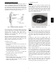
General Fig. 1 and Fig. 2 show general unit arrangement and access locations. CONTROL BOX INDOOR BLOWER ACCESS COMPRESSORS (D08-09 only) C09190 Fig.
SUPPLY FAN (BLOWER) SECTION Outside Air Hood Outside air hood inlet screens are permanent aluminum-- mesh type filters. Check these for cleanliness. Remove the screens when cleaning is required. Clean by washing with hot low-- pressure water and soft detergent and replace all screens before restarting the unit. Observe the flow direction arrows on the side of each filter frame. WARNING ! ELECTRICAL SHOCK HAZARD Failure to follow this warning could cause personal injury or death.
48J 460, 575-v Units 208/230-v Units C09263 Fig. 7 - EMC Unit Wiring Table 1 – 548J Standard Static Motor Tap Programing (percent of full--load torque) ECM Motor – The direct-- drive motor is an X13 Electronically Commutated motor (ECM). An ECM contains electronic circuitry to convert single-- phase line AC voltage into a 3-- phase DC voltage to power the motor circuit. The motor circuit is a DC brushless design with a permanent magnet rotor.
Table 2 – Motor Test Volts 548J Unit Voltage 208/230 460 575 Motor Voltage 230 230 460 Min---Max Volts 190--- 250 210--- 250 420--- 500 5. Apply a jumper at unit control terminals R to G to initiate a demand for motor operation. Check for 24-- v output at defrost board terminal IFO. 6. Check for proper control signal voltage at motor signal leads VIO and BRN. Signal should be 22 to 28-- v. 7. Disconnect unit main power. 8. Reconnect motor power and control signal leads at the motor terminals. 9.
Adjustable-- Pitch Pulley on Motor This fan system uses bearings featuring concentric split locking collars. The collars are tightened through a cap screw bridging the split portion of the collar. The cap screw has a Torx T25 socket head. To tighten the locking collar: Hold the locking collar tightly against the inner race of the bearing and torque the cap screw to 65-- 70 in-- lb (7.4-- 7.9 Nm). See Fig. 10.
HEAT PUMP REFRIGERATION SYSTEM ! WARNING 548J UNIT OPERATION AND SAFETY HAZARD Failure to follow this warning could cause personal injury, death and/or equipment damage. This system uses PuronR refrigerant which has higher pressures than R-- 22 and other refrigerants. No other refrigerant may be used in this system. Gauge set, hoses, and recovery system must be designed to handle Puron refrigerant. If unsure about equipment, consult the equipment manufacturer.
7. Secure inner and outer coil rows together with a field-- supplied fastener. 8. Reposition the outer coil section and remove the coil corner post from between the top panel and center post. Reinstall the coil corner post and replace all screws. Totaline Environmentally Sound Coil Cleaner Application Equipment S 2 1/2 gallon garden sprayer S Water rinse with low velocity spray nozzle OUTDOOR COIL UNIT DAMAGE HAZARD Failure to follow this caution may result in corrosion and damage to the unit.
8. 9. 10. Each heat pump refrigeration system includes a compressor, accumulator, reversing valve, dual-- function outdoor coil with vapor header check valve, cooling liquid line with filter drier and check valve, dual-- function indoor coil with vapor header check valve, and heating liquid line with check valve and strainer. Unit sizes 04A-- 07A have a single compressor-- circuit; unit sizes 08D and 09D have two compressor-- circuits. See Fig.
To Evaporator Coil Circuits To Condensing Circuit Metering Orifice From Transfer Header From Liquid Header C09231 C09229 Fig. 15 - Heat Pump Acutrol — Flow as Evaporator Function Converging circuit flow in the condenser-- function operation is accomplished with the check valve in the vapor header and the liquid transfer header connected to the side ports on all but one of the Acurator tee nipples in each circuit.
Table 5 – Defrost Mode start the circuit in a Cooling Mode (jumper R to Y1 or Y2) and observe the frosting pattern on the face of the indoor coil. A frost pattern should develop uniformly across the face of the indoor coil starting at each tube at the Acutrol nipple locations.
This unit is designed for use with Puron (R-- 410A) refrigerant. Do not use any other refrigerant in this system. Puron (R-- 410A) refrigerant is provided in pink (rose) colored cylinders. These cylinders are available with and without dip tubes; cylinders with dip tubes will have a label indicating this feature. For a cylinder with a dip tube, place the cylinder in the upright position (access valve at the top) when removing liquid refrigerant for charging.
548J COOLING CHARGING CHARTS C09184 Fig. 20 -- Cooling Charging Charts-- 548J*04A C09185 Fig. 20 (cont.
548J C09186 Fig. 20 (cont.) -- Cooling Charging Charts -- 548J*06A C09187 Fig. 20 (cont.
548J C09188 Fig. 20 (cont.) -- Cooling Charging Charts -- 548J*08D C09189 Fig. 20 (cont.
Compressor Rotation ! CAUTION PERSONAL INJURY HAZARD Failure to follow this caution may result in personal injury. Filter Drier Replace whenever refrigerant system is exposed to atmosphere. Only use factory specified liquid-- line filter driers with working pressures no less than 650 psig. Do not install a suction-- line filter drier in liquid line. A liquid-- line filter drier designed for use with Puron refrigerant is required on every unit. Outdoor Fan Location 1. Shut off unit power supply.
Table 6 – Heating and Cooling Troubleshooting PROBLEM Compressor and Outdoor Fan Will Not Start. CAUSE REMEDY Power failure. Call power company. Fuse blown or circuit breaker tripped. Replace fuse or reset circuit breaker. Determine root cause. Defective thermostat, contactor, transformer, control relay, or capacitor. Replace component. Insufficient line voltage. Determine cause and correct. Incorrect or faulty wiring. Check wiring diagram and rewire correctly. Thermostat setting too high.
CONVENIENCE OUTLETS ! Mount the weatherproof cover to the backing plate as shown in Fig. 23. Remove two slot fillers in the bottom of the cover to permit service tool cords to exit the cover. Check for full closing and latching. WARNING ELECTRICAL OPERATION HAZARD Failure to follow this warning could result in personal injury or death. Units with convenience outlet circuits may use multiple disconnects. Check convenience outlet for power status before opening unit for service.
if the GFCI receptacle does not trip as required. Press the RESET button to clear the tripped condition. Terminals are clearly marked on the board surface. See Fig 25. 548J The CTB contains no software and no logic. But it does include seven configuration jumpers that are cut to configure the board to read external optional and accessory controls, including that the unit is a heat pump.
The compressor has an internal protector to protect it against excessively high discharge gas temperatures. High Pressure Switch The system is provided with a high pressure switch mounted on the discharge line. The switch is stem-- mounted and brazed into the discharge tube. Trip setting is 630 psig +/-- 10 psig (4344 +/-- 69 kPa) when hot. Reset is automatic at 505 psig (3482 kPa).
C09276 548J Fig.
Auxiliary (Electric) Heat control — The 548J unit can be equipped with one or two auxiliary electric heaters, to provide a second stage of Heating. The DFB will energize this Heating system for a Stage 2 Heating command (heaters operate concurrently with both compressors in the Stage 2 Heating cycle), for an Emergency Heating sequence (compressors are off and only the electric heaters are energized) and also during the Defrost cycle (to eliminate a “cold blow” condition in the space).
Shorting the jumpers for a period of 5 to 20 secs bypasses the remaining continuous run period and places the unit in a Forced Defrost mode. If the controlling DFT is closed when this mode is initiated, the unit will complete a normal defrost period that will terminate when the controlling DFT opens or the 10 minute defrost cycle limit is reached. If the controlling DFT is open when this mode is initiated, the Defrost cycle will run for 30 secs. Both modes end at the end of the Defrost cycle.
Single Point Boxes and Supplementary Fuses — When the unit MOCP device value exceeds 60-- A, unit-- mounted supplementary fuses are required for each heater circuit. These fuses are included in accessory Single Point Boxes, with power distribution and fuse blocks. The single point box will be installed directly under the unit control box, just to the left of the partition separating the indoor section (with electric heaters) from the outdoor section. The Single Point Box has a hinged access cover. See Fig.
SMOKE DETECTORS Sensor Smoke detectors are available as factory-- installed options on 548J models. Smoke detectors may be specified for Supply Air only or for Return Air without or with economizer or in combination of Supply Air and Return Air. Return Air smoke detectors are arranged for vertical return configurations only. All components necessary for operation are factory-- provided and mounted.
For installations using two sensors, the duct smoke detector does not differentiate which sensor signals an alarm or trouble condition. Smoke Detector Locations Supply Air — The Supply Air smoke detector sensor is located to the left of the unit’s indoor (supply) fan. See Fig. 37. Access is through the fan access panel. There is no sampling tube used at this location. The sampling tube inlet extends through the side plate of the fan housing (into a high pressure area).
6. For units with an economizer, the sampling tube is integrated into the economizer housing but the connection of the flexible tubing to the sampling tube is the same. Highlight B: Smoke detector NC contact set will open on smoke alarm condition, de-- energizing the ORN conductor. Highlight C: 24-- v power signal via ORN lead is removed at Smoke Detector input on CTB (Control Terminal Board); all unit operations cease immediately.
Sensor and Controller Tests Dirty Controller Test Sensor Alarm Test The dirty controller test checks the controller’s ability to initiate a dirty sensor test and indicate its results. ! OPERATIONAL TEST HAZARD Failure to follow this caution may result in personnel and authority concern. Pressing the controller’s test/reset switch for longer than seven seconds will put the duct detector into the alarm state and activate all automatic alarm responses.
! CAUTION OPERATIONAL TEST HAZARD Failure to follow this caution may result in personnel and authority concern. Changing the dirty sensor test operation will put the detector into the alarm state and activate all automatic alarm responses. Before changing dirty sensor test operation, disconnect all auxiliary equipment from the controller and notify the proper authorities if connected to a fire alarm system.
Table 13 – Detector Indicators Alarm LED Trouble LED Dirty LED Power LED DESCRIPTION Resets the sensor when it is in the alarm or trouble state. Activates or tests the sensor when it is in the normal state. Indicates the sensor is in the alarm state. Indicates the sensor is in the trouble state. Indicates the amount of environmental compensation used by the sensor (flashing continuously = 100%) Indicates the sensor is energized.
Trouble Alarm Power Test/reset switch 548J Fig. 45 - Controller Assembly C07298 NOTE: All troubles are latched by the duct smoke detector. The trouble condition must be cleared and then the duct smoke detector must be reset in order to restore it to the normal state. Resetting Alarm and Trouble Condition Trips: Manual reset is required to restore smoke detector systems to Normal operation.
RTU--MP CONTROL SYSTEM The RTU-- MP controller, see Fig. 46, provides expanded stand-- alone operation of the HVAC system plus connection and control through communication with several Building Automation Systems (BAS) through popular third-- party network systems. The available network systems are BACnet MP/TP, Modbus and Johnson J2. Communication with LonWorks is also possible by adding an accessory interface card to the RTU-- MP.
Fig.
548J Fig.
Table 14 – RTU-- MP Controller Inputs and Outputs 548J POINT NAME Space Temperature Sensor Supply Air Temperature Local Outside Air Temperature Sensor Space Temperature Offset Pot Indoor Air Quality Outdoor Air Quality Safety Chain Feedback Compressor Safety Fire Shutdown Enthalpy Switch Humidistat Input Status Space Relative Humidity Outside Air Relative Humidity Supply Fan Status Filter Status Remote Occupancy Input Economizer Commanded Position Supply Fan Relay State Compressor 1 Relay State Compressor
Table 15 – Thermistor Resistance vs Temperature Values for Space Temperature Sensor, Supply Air Temperature Sensor, and Outdoor Air Temperature Sensor TEMP (F) --- 40 --- 31 --- 22 --- 13 --- 4 5 14 23 32 41 50 59 68 77 86 95 104 113 122 131 140 149 158 RESISTANCE (Ohms) 335,651 242,195 176,683 130,243 96,974 72,895 55,298 42,315 32,651 25,395 19,903 15,714 12,494 10,000 8,056 6,530 5,325 4,367 3,601 2,985 2,487 2,082 1,752 NOTE: The sensor must be mounted in the discharge airstream downstream of the cool
BRN (COM) J20-1 SEN BLK (STO) SENSOR WIRING BLU (SPT) J20-2 SEN Fig. 52 - RTU-- MP T-- 55 Sensor Connections C08460 OR Connect T-- 56 - See Fig. 53 for T-- 56 internal connections. Install a jumper between SEN and SET terminals as illustrated. Connect T-- 56 terminals to RTU-- MP J20-- 1, J20-- 2 and J20-- 3 per Fig. 54. SET SEN OPB COM- PWR+ POWER WIRING 24 VAC 548J NOTE: Must use a separate isolated transformer. C07132 1 2 3 4 SEN SW1 5 6 RED(+) WHT(GND) BLK(-) Fig.
Differential Enthalpy Control — Differential enthalpy control is provided by sensing and comparing the outside air and return air enthalpy conditions. Install the outdoor air enthalpy control as described above. Add and install a return air enthalpy sensor. Return Air Enthalpy Sensor — Mount the return-- air enthalpy sensor (33CSENTSEN) in the return-- air section of the ecomomizer. The return air sensor is wired to the enthalpy controller (33CSENTHSW). See Fig. 57.
548J Outdoor Air Quality Sensor (PNO 33ZCSENCO2 plus weatherproof enclosure) — The outdoor air CO2 sensor is designed to monitor carbon dioxide (CO2) levels in the outside ventilation air and interface with the ventilation damper in an HVAC system. The OAQ sensor is packaged with an outdoor cover. See Fig. 60. The outdoor air CO2 sensor must be located in the economizer outside air hood. COVER REMOVED SIDE VIEW Fig.
the LonWorks packets. In order to reduce the cost of adding that hardware on every module, a separate LonWorks Option Card (LON-- OC) was designed to connect to the RTU-- MP. This accessory card is needed for LonWorks and has to be ordered and connected using the ribbon cable to plug J15. The RTU-- MP’s baud rate must be set to 38.4k to communicate with the LON-- OC. The address switches (SW1 & SW2) are not used with LonWorks.
548J Fig. 64 - BACview6 Handheld Connections C07170 RTU--MP Troubleshooting Communication LEDs The LEDs on the RTU-- MP (see Fig. 46) indicate if the controller is speaking to the devices on the network. The LEDs should reflect communication traffic based on the baud rate set. The higher the baud rate the more solid the LEDs will appear. See Table 16 for further information. Table 16 – RTU-- MP LEDs The LEDs on the RTU ---MP show the status of certain functions Status is...
Table 17 – Troubleshooting Alarms POINT NAME BACnet OBJECT NAME Safety Chain Alarm safety_chain Alarm Generated Immediate Shutdown Automatic Over load Indoor Fan or Electric Heater overheat. Fire Shutdown Alarm fire_alarm Alarm Generated Immediate Shutdown Automatic Smoke detected by smoke detector or configuration incorrect Space Temp Sensor Failure spt_alarm Alarm Generated Immediate Shutdown Automatic Faulty, shorted, or open thermistor caused by wiring error or loose connection.
548J Alarms Alarms can be checked through the network and/or the local access. All the alarms are listed in Table 17 with name, object name, action taken by control, reset method, and probable cause. There are help screens for each alarm on the local access display and listed in Form 48-- 50H-- T-- 2T, Appendix A: Help Screens. Some alarms are explained in detail below. Safety Chain Alarm This alarm occurs immediately if the supply-- fan internal overload trips or if an electric-- heat limit switch trips.
S Max Masters: Defines the highest MS/TP Master MAC address on this MS/TP network. For example, if there are 3 master nodes on an MS/TP network, and their MAC addresses are 1, 8, and 16, then Max Masters would be set to 16 (since this is the highest MS/TP MAC address on the network). This property optimizes MS/TP network communications by preventing token passes and “poll for master” requests to non-- existent Master nodes (i.e.
Table 18 – Manufacture Date When troubleshooting, you may need to know a control module’s manufacture date. Notes Module status report (modstat) To obtain a modstat with BACview6: 1. Press Function (FN) key and hold. 2. Then press period (.) 3. Release both buttons. The report shows the date under Main board hardware.
ECONOMIZER SYSTEMS N2 The 548J units may be equipped with a factory-- installed or accessory (field-- installed) economizer system. Two types are available: with a logic control system (EconoMi$er IV) and without a control system (EconoMi$er2). See Fig. 66 and Fig. 67 for component locations on each type. See Fig. 68 and Fig. 69 for economizer section wiring diagrams. Both economizers use direct-- drive damper actuators.
548J Economizer 2 Position Damper Unit Without Economizer or 2 Position Damper C08631 Fig. 68 - EconoMi$er IV Wiring BLACK 4 TRANSFORMER GROUND 3 5 BLUE 500 OHM RESISTOR 2 8 VIOLET 6 NOTE 1 PINK 7 RUN OAT SENSOR RED NOTE 3 1 24 VAC 10 YELLOW 50HJ540573 ACTUATOR ASSEMBLY 11 9 DIRECT DRIVE ACTUATOR 4-20mA SIGNAL WHITE 12 4-20 mA TO J9 ON PremierLink BOARD ECONOMISER2 PLUG NOTES: 1. Switch on actuator must be in run position for economizer to operate. 2.
Table 21 – EconoMi$er IV Input/Output Logic Below set (DCV LED Off) Above set (DCV LED On) Compressor Outdoor Return High (Free Cooling LED Off) Low Low (Free Cooling LED On) High High (Free Cooling LED Off) Low Low (Free Cooling LED On) High Y1 Y2 On On Off On On Off On On Off On On Off On Off Off On Off Off On Off Off On Off Off Stage Stage 1 2 On On Off On Off Off On On Off On Off Off On Off Off Off Off Off On Off Off Off Off Off OUTPUTS N Terminal† Occupied Damper Unoccupied Minimu
SUPPLY AIR TEMPERATURE SENSOR MOUNTING LOCATION SUPPLY AIR TEMPERATURE SENSOR C06033 The temperature sensor looks like an eyelet terminal with wires running to it. The sensor is located in the “crimp end” and is sealed from moisture. Outdoor Air Lockout Sensor The EconoMi$er IV is equipped with an ambient temperature lockout switch located in the outdoor airstream which is used to lock out the compressors below a 42_F (6_C) ambient temperature. (See Fig. 66.
FLOW IN CUBIC FEET PER MINUTE (cfm) controller. The setpoints are A, B, C, and D. (See Fig. 76.) The factory-installed 620-ohm jumper must be in place across terminals SR and SR+ on the EconoMi$er IV controller (see Fig. 68). In this mode of operation, the outdoor-air temperature is compared to the return-air temperature and the lower temperature airstream is used for cooling. When using this mode of changeover control, turn the enthalpy setpoint potentiometer fully clockwise to the D setting. (See Fig.
CO2 SENSOR MAX RANGE SETTING EXH N1 P Min Pos T1 DCV 2V AQ SR+ 548J SR + Max 10V 1 _ 2V 2 5 DCV SO+ SO 24 Vac COM Open T AQ1 24 Vac HOT 6000 Set 10V 2V EXH P1 TR1 RANGE CONFIGURATION (ppm) N TR DCV Set 10V Free Cool B C A D 3 EF Fig. 77 - EconoMi$er IV Control 5000 4000 800 ppm 900 ppm 1000 ppm 1100 ppm 3000 2000 1000 0 4 2 3 4 5 6 7 8 DAMPER VOLTAGE FOR MAX VENTILATION RATE EF1 C06039 Fig.
(TO x OA ) + (TR 100 x RA ) =TM 100 TO = Outdoor-Air Temperature OA = Percent of Outdoor Air TR = Return-Air Temperature RA = Percent of Return Air TM = Mixed-Air Temperature As an example, if local codes require 10% outdoor air during occupied conditions, outdoor-air temperature is 60_F, and return-air temperature is 75_F. (60 x .10) + (75 x .90) = 73.5_F 2. Disconnect the supply air sensor from terminals T and T1. 3. Ensure that the factory-installed jumper is in place across terminals P and P1.
8J graph with the left side of the chart to determine that the range configuration for the CO2 sensor should be 1800 ppm. The EconoMi$er IV controller will output the 6.7 volts from the CO2 sensor to the actuator when the CO2 concentration in the space is at 1100 ppm. The DCV setpoint may be left at 2 volts since the CO2 sensor voltage will be ignored by the EconoMi$er IV controller until it rises above the 3.6 volt setting of the minimum position potentiometer.
This procedure is used to prepare the EconoMi$er IV for troubleshooting. No troubleshooting or testing is done by performing the following procedure. NOTE: This procedure requires a 9-- v battery, 1.2 kilo-- ohm resistor, and a 5.6 kilo-- ohm resistor which are not supplied with the EconoMi$er IV. IMPORTANT: Be sure to record the positions of all potentiometers before starting troubleshooting. 1. Disconnect power at TR and TR1. All LEDs should be off. Exhaust fan contacts should be open. 2.
5. Return EconoMi$er IV settings and wiring to normal after completing troubleshooting. EconoMi$er IV Troubleshooting Completion This procedure is used to return the EconoMi$er IV to operation. No troubleshooting or testing is done by performing the following procedure. 548J 1. Disconnect power at TR and TR1. 2. Set enthalpy potentiometer to previous setting. 3. Set DCV maximum position potentiometer to previous setting. 4.
548J Fig.
PRE--START--UP 548J ! ! WARNING PERSONAL INJURY AND ENVIRONMENTAL HAZARD Failure to follow this warning could result in personal injury or death. Relieve pressure and recover all refrigerant before system repair or final unit disposal. Wear safety glasses and gloves when handling refrigerants. Keep torches and other ignition sources away from refrigerants and oils. PERSONAL INJURY HAZARD Failure to follow this warning could result in personal injury or death. 1.
Check all electrical connections in unit control boxes. Tighten as required. Refrigerant Service Ports Each unit system has two 1/4” SAE flare (with check valves) service ports: one on the suction line, and one on the compressor discharge line. Be sure that caps on the ports are tight. Compressor Rotation On 3-- phase units with scroll compressors, it is important to be certain compressor is rotating in the proper direction. To determine whether or not compressor is rotating in the proper direction: 1.
service test. Indoor fans and outdoor fans are controlled normally to maintain proper unit operation. All normal cooling alarms and alerts are functional. NOTE: Circuit A is always operated with Circuit B due to outdoor fan control on Circuit A. Always test Circuit A first, and leave it on to test other Circuits. The Heating submenu is used to change output status for the individual heat stages, gas or electric. The fans and cooling service test outputs are reset to OFF for the heating service test.
Input 1 Function This input is an analog input and can be configured to be one of five different inputs: No Sensor, IAQ Sensor, OAQ Sensor, Space RH Sensor, or Outdoor RH Sensor. Input 1 is wired to pin J4-- 5. Factory Default = No Sensor Input 2 Function This input is an analog input and can be configured to be one of five different inputs: No Sensor, IAQ Sensor, OAQ Sensor, Space RH Sensor, or Outdoor RH Sensor. Input 2 is wired to pin J4-- 2.
548J Economizer Economizer Exists This point tells the controller if there is an economizer installed on the unit. Factory Default = NO if no economizer YES if there is an economizer installed Economizer Minimum Position This defines the lowest economizer position when the indoor fan is running and the building is occupied.
When Cooling Stage 2 is satisfied, thermostat Y2 opens. Compressor 2 contactor (C2) is de-- energized; Compressor 2 stops. RVS2 remains energized. When Cooling Stage 1 is satisfied, thermostat Y1 opens. Compressor 1 contactor (C1) is de-- energized; Compressor 1 stops. Outdoor fan relay OFR is de-- energized; outdoor fans stop. After the Fan Delay period, the Indoor fan contactor IFC is de-- energized; indoor fan stops (unless Continuous Fan operation has been selected). RVS1 remains energized.
de-- energized as the dampers close below the PE-- On setpoint. Damper movement from full closed to full open (or vice versa) will take between 11/2 and 21/2 minutes. Heating With EconoMi$er IV During Occupied mode operation, indoor fan operation will be accompanied by economizer dampers moving to Minimum Position setpoint for ventilation. If indoor fan is off, dampers will close. During Unoccupied mode operation, dampers will remain closed unless a DCV demand is received.
RTU--MP Sequence of Operation The RTU-- MP will control the compressor, economizer and heating outputs based on its own space temperature input and setpoints. An optional CO2 IAQ sensor mounted in the space can influence the economizer minimum position. The RTU-- MP has its own hardware clock that is set automatically when the software is installed on the board. The RTU-- MP’s default is to control to occupied setpoints all the time, until a type of occupancy control is set.
548J look for a contact closure whenever the Supply Fan Relay is on. If it is not enabled then it will always be the same state as the Supply Fan Relay. The cooling, economizer, heating, dehumidification, CO2 and power exhaust routines will use this input point for fan status. Cooling The compressor outputs are controlled by the Cooling Control PID Loop and Cooling Stages Capacity algorithm.
greatest value becomes the final minimum damper position of the economizer output. If the calculated IAQ minimum position is greater than the IAQ maximum damper position configuration then it will be clamped to the configured value.
APPENDIX I. MODEL NUMBER SIGNIFICANCE MODEL NUMBER NOMENCLATURE 1 2 3 4 5 5 4 8 J P 0 ____________ 6 7 8 9 6 A 0 ______ 10 11 12 13 14 15 16 17 18 0 0 A 0 B 0 A A -- ________ ______ Unit Type Design Revision 548J = High Eff.
APPENDIX II. PHYSICAL DATA 548J*05A 548J*06A 548J*07A 1 / 1 / Scroll 9--- 8 / --42 / --Accutrol 630 / 505 27 / 44 1 / 1 / Scroll 11--- 11 / --42 / --Accutrol 630 / 505 27 / 44 1 / 1 / Scroll 12--- 13 / --42 / --Accutrol 630 / 505 27 / 44 1 / 1 / Scroll 16--- 13 / --56 / --Accutrol 630 / 505 27 / 44 Cu / Al 3/8” RTPF 3 / 15 5.5 3/4” Cu / Al 3/8” RTPF 4 / 15 5.5 3/4” Cu / Al 3/8” RTPF 4 / 15 7.3 3/4” Cu / Al 3/8” RTPF 4 / 15 7.
APPENDIX II. PHYSICAL DATA (cont.) 548J*08D 548J*09D 2 / 2 / Scroll 10--- 3 / 10--- 3 42 / 42 Accutrol 630 / 505 27 / 44 2 / 2 / Scroll 11--- 2 / 11--- 2 42 / 42 Accutrol 630 / 505 27 / 44 Cu / Al 3/8” RTPF 3 / 15 11.1 3/4” Cu / Al 3/8” RTPF 4 / 15 11.1 3/4” Standard Static 3 phase Motor Qty / Drive Type Max BHP RPM Range Motor Frame Size Fan Qty / Type Fan Diameter (in) 1 / Belt 1.2 460--- 652 56 1 / Centrifugal 15 x 15 1 / Belt 1.2 460--- 652 56 1 / Centrifugal 15 x 15 Medium Static 3 phase 7.
APPENDIX III. FAN PERFORMANCE General Fan Performance Notes: 548J 1. Interpolation is permissible. Do not extrapolate. 2. External static pressure is the static pressure difference between the return duct and the supply duct plus the static pressure caused by any FIOPs or accessories. 3. Tabular data accounts for pressure loss due to clean filters, unit casing, and wet coils. Factory options and accessories may add static pressure losses. 4. The Fan Performance tables offer motor/drive recommendations.
APPENDIX III. FAN PERFORMANCE Table 25 – 548J*04A ELECTRIC DRIVE, X13 MOTOR, 3 TON HORIZONTAL SUPPLY SPEED (TORQUE) TAP 548J 1 2 3 4 5 CFM ESP BHP 900 975 1050 1125 1200 1275 1350 1425 1500 900 975 1050 1125 1200 1275 1350 1425 1500 900 975 1050 1125 1200 1275 1350 1425 1500 900 975 1050 1125 1200 1275 1350 1425 1500 900 975 1050 1125 1200 1275 1350 1425 1500 0.70 0.60 0.50 0.39 0.29 0.21 0.12 0.03 --0.85 0.76 0.66 0.55 0.46 0.36 0.27 0.17 0.07 1.02 0.94 0.86 0.79 0.71 0.61 0.51 0.40 0.29 1.12 1.
APPENDIX III. FAN PERFORMANCE (cont.) SPEED (TORQUE) TAP 1 2 3 4 5 CFM ESP BHP 1200 1300 1400 1500 1600 1700 1800 1900 2000 1200 1300 1400 1500 1600 1700 1800 1900 2000 1200 1300 1400 1500 1600 1700 1800 1900 2000 1200 1300 1400 1500 1600 1700 1800 1900 2000 1200 1300 1400 1500 1600 1700 1800 1900 2000 0.75 0.63 0.48 0.33 0.19 0.05 ------0.97 0.88 0.77 0.64 0.50 0.36 0.21 0.06 --0.98 0.91 0.82 0.71 0.58 0.45 0.31 0.16 0.03 0.98 0.92 0.86 0.79 0.70 0.62 0.52 0.37 0.21 1.02 0.97 0.92 0.87 0.82 0.
APPENDIX III. FAN PERFORMANCE (cont.) Table 29 – 548J*06A ELECTRIC DRIVE, X13 MOTOR, 5 TON HORIZONTAL SUPPLY SPEED (TORQUE) TAP 548J 1 2 3 4 5 CFM ESP BHP 1500 1625 1750 1875 2000 2125 2250 2375 2500 1500 1625 1750 1875 2000 2125 2250 2375 2500 1500 1625 1750 1875 2000 2125 2250 2375 2500 1500 1625 1750 1875 2000 2125 2250 2375 2500 1500 1625 1750 1875 2000 2125 2250 2375 2500 1.19 1.01 0.82 0.60 0.38 0.16 ------1.40 1.25 1.08 0.90 0.67 0.44 0.20 ----1.41 1.28 1.13 0.96 0.74 0.51 0.27 0.02 --1.
APPENDIX III. FAN PERFORMANCE (cont.) Table 31 – 548J*04A CFM 900 975 1050 1125 1200 1275 1350 1425 1500 3 TON HORIZONTAL SUPPLY BHP 0.13 0.15 0.18 0.20 0.23 0.26 0.30 0.34 0.38 AVAILABLE EXTERNAL STATIC PRESSURE (IN. WG) 0.4 0.6 0.8 RPM BHP RPM BHP RPM 707 0.23 817 0.34 913 727 0.25 835 0.37 929 747 0.28 853 0.40 946 768 0.31 872 0.43 964 790 0.34 892 0.47 982 812 0.38 912 0.51 1001 835 0.42 933 0.55 1020 859 0.46 955 0.60 1040 883 0.51 977 0.65 1061 BHP 0.47 0.50 0.53 0.57 0.61 0.65 0.70 0.75 0.
APPENDIX III. FAN PERFORMANCE (cont.) Table 33 – 548J*05A CFM 548J 1200 1300 1400 1500 1600 1700 1800 1900 2000 4 TON HORIZONTAL SUPPLY BHP 0.23 0.28 0.33 0.38 0.45 0.52 0.60 0.69 0.78 AVAILABLE EXTERNAL STATIC PRESSURE (IN. WG) 0.4 0.6 0.8 RPM BHP RPM BHP RPM 790 0.34 892 0.47 982 820 0.39 919 0.52 1007 851 0.45 947 0.58 1034 883 0.51 977 0.65 1061 916 0.58 1007 0.73 1089 949 0.66 1038 0.81 1118 984 0.75 1069 0.90 1148 1019 0.84 1102 1.00 1179 1054 0.94 1135 1.11 1210 BHP 0.61 0.67 0.73 0.80 0.89 0.
APPENDIX III. FAN PERFORMANCE (cont.) Table 35 – 548J*06A CFM 1500 1625 1750 1875 2000 2125 2250 2375 2500 5 TON HORIZONTAL SUPPLY RPM 840 876 912 950 988 1027 1067 1107 1148 AVAILABLE EXTERNAL STATIC PRESSURE (IN. WG) 0.4 0.6 0.8 BHP RPM BHP RPM 0.46 937 0.60 1023 0.54 970 0.68 1054 0.63 1004 0.78 1087 0.72 1039 0.88 1120 0.83 1075 1.00 1154 0.95 1112 1.13 1189 1.08 1149 1.27 1224 1.23 1187 1.43 1261 1.39 1226 1.59 1297 BHP 0.75 0.84 0.94 1.05 1.18 1.31 1.46 1.63 1.
APPENDIX III. FAN PERFORMANCE (cont.) Table 37 – 548J*07A CFM 548J 1800 1950 2100 2250 2400 2550 2700 2850 3000 6 TON HORIZONTAL SUPPLY RPM 927 973 1019 1067 1115 1164 1214 1264 1315 AVAILABLE EXTERNAL STATIC PRESSURE (IN. WG) 0.4 0.6 0.8 BHP RPM BHP RPM 0.66 1018 0.82 1100 0.79 1061 0.95 1140 0.92 1104 1.10 1182 1.08 1149 1.27 1224 1.26 1195 1.46 1268 1.46 1241 1.67 1312 1.67 1289 1.90 1358 1.92 1336 2.15 1404 2.18 1385 2.43 1451 BHP 0.98 1.13 1.29 1.46 1.66 1.88 2.12 2.39 2.
APPENDIX III. FAN PERFORMANCE (cont.) Table 39 – 548J*08D CFM 2250 2438 2625 2813 3000 3188 3375 3563 3750 7.5 TON HORIZONTAL SUPPLY BHP 0.28 0.34 0.40 0.47 0.55 0.65 0.75 0.86 0.99 AVAILABLE EXTERNAL STATIC PRESSURE (IN. WG) 0.4 0.6 0.8 RPM BHP RPM BHP RPM 509 0.40 587 0.52 659 525 0.46 600 0.59 669 543 0.53 614 0.67 680 561 0.61 629 0.76 693 580 0.70 646 0.86 707 600 0.80 663 0.96 722 621 0.91 681 1.08 738 642 1.03 700 1.21 755 664 1.17 720 1.35 773 BHP 0.66 0.73 0.82 0.91 1.02 1.13 1.26 1.39 1.
APPENDIX III. FAN PERFORMANCE (cont.) Table 41 – 548J*09D CFM 548J 2550 2763 2975 3188 3400 3613 3825 4038 4250 8.5 TON HORIZONTAL SUPPLY BHP 0.39 0.47 0.57 0.68 0.80 0.94 1.09 1.26 1.45 AVAILABLE EXTERNAL STATIC PRESSURE (IN. WG) 0.4 0.6 0.8 RPM BHP RPM BHP RPM 546 0.52 618 0.66 684 567 0.61 635 0.76 699 589 0.72 654 0.87 716 613 0.83 675 1.00 733 637 0.96 696 1.14 752 662 1.11 719 1.29 773 688 1.27 742 1.46 794 714 1.45 766 1.65 816 741 1.65 790 1.86 838 BHP 0.80 0.91 1.03 1.17 1.31 1.48 1.66 1.85 2.
APPENDIX III. FAN PERFORMANCE (cont.) 3 phase 3 phase 3 phase 3 phase 3 phase 3 phase 09 08 07 06 05 04 Unit Motor/Drive Combo Motor Pulley turns open 2 2.5 3 0 0.5 1 1.5 3.5 4 4.
APPENDIX IV. ELECTRICAL INFORMATION Table 44 – 548J*04A 548J V-- Ph-- Hz VOLTAGE RANGE 1-- Stage Cooling COMP (ea) OFM (ea) IFM MIN MAX RLA LRA WATTS FLA TYPE 208--1--60 230--1--60 187 187 253 253 17.9 17.9 112 112 190 190 0.9 0.9 208--3--60 187 253 13.2 88 190 0.9 230--3--60 187 253 13.2 88 190 0.9 460--3--60 414 506 6.0 44 190 0.5 575--3--60 518 633 NA NA 190 0.
APPENDIX IV. ELECTRICAL INFORMATION (cont.) V ---Ph---Hz 1-- Stage Cooling VOLTAGE RANGE MIN MAX COMP (ea) RLA LRA OFM (ea) WATTS IFM FLA 208--- 3--- 60 187 253 19.0 123 325 1.5 230--- 3--- 60 187 253 19.0 123 325 1.5 460--- 3--- 60 414 506 9.7 62 325 0.8 575--- 3--- 60 518 633 7.4 50 325 0.
APPENDIX IV. ELECTRICAL INFORMATION (cont.) NOM. V--- PH--- HZ ELECTRIC HEATER IFM TYPE STD 548J 208/230--- 1--- 60 UNIT Table 50 – Unit Wire/MOCP Sizing Data 548J*04A 208/230--- 3--- 60 STD MED HIGH 460--- 3--- 60 STD MED NO P.E. Nom (kW) FLA --- w/ P.E. (pwrd fr/unit) DISC. SIZE MCA MOCP FLA LRA --- 30.7 45 30 3.3/4.4 15.9/18.3 50.6/53.6 60/60 4.9/6.5 23.5/27.1 60.1/64.6 6.5/8.7 31.4/36.3 69.9/76.1 7.9/10.5 37.9/43.8 9.8/13.0 DISC. SIZE MCA MOCP 121 32.
APPENDIX IV. ELECTRICAL INFORMATION (cont.) ELECTRIC HEATER IFM TYPE STD 548J*04A 208/230--- 3--- 60 STD MED HIGH 460--- 3--- 60 STD MED NO P.E. Nom (kW) FLA --- w/ P.E. (pwrd fr/unit) DISC. SIZE MCA MOCP FLA LRA --- 35.5 50 36 3.3/4.4 15.9/18.3 55.4/58.4 60/60 4.9/6.5 23.5/27.1 64.9/69.4 6.5/8.7 31.4/36.3 74.7/80.9 7.9/10.5 37.9/43.8 9.8/13.0 DISC. SIZE MCA MOCP 126 37.4 50 38 128 54/57 142/144 57.3/60.3 60/70 56/59 144/146 70/80 63/67 150/153 66.8/71.
APPENDIX IV. ELECTRICAL INFORMATION (cont.) NOM. V--- PH--- HZ 548J*05A 208/230--- 3--- 60 208/230--- 3--- 60 548J 208/230--- 1--- 60 UNIT Table 50 — Unit Wire/MOCP Sizing Data (cont) ELECTRIC HEATER IFM TYPE STD STD MED HIGH 460--- 3--- 60 STD MED 575--- 3--- 60 HIGH NO C.O. or UNPWRD C.O. NO P.E. Nom (kW) FLA --- w/ P.E. (pwrd fr/unit) DISC. SIZE MCA MOCP FLA LRA --- 36.2 50 35 3.3/4.4 15.9/18.3 56.0/59.0 60/60 DISC. SIZE MCA MOCP 128 38.
APPENDIX IV. ELECTRICAL INFORMATION (cont.) ELECTRIC HEATER IFM TYPE STD 208/230--- 3--- 60 STD MED 548J*05A HIGH 460--- 3--- 60 STD MED 575--- 3--- 60 HIGH w/ PWRD C.O. NO P.E. Nom (kW) FLA --- w/ P.E. (pwrd fr/unit) DISC. SIZE MCA MOCP FLA LRA --- 41.0 60 41 3.3/4.4 15.9/18.3 60.8/63.8 70/80 DISC. SIZE MCA MOCP 133 42.9 60 43 135 59/62 149/151 62.7/65.7 80/80 61/64 151/153 FLA LRA 6.5/8.7 31.4/36.3 80.2/86.3 90/90 77/83 164/169 82.1/88.
APPENDIX IV. ELECTRICAL INFORMATION (cont.) NOM. V--- PH--- HZ ELECTRIC HEATER IFM TYPE STD 548J 208/230--- 1--- 60 UNIT Table 50 — Unit Wire/MOCP Sizing Data (cont) 208/230--- 3--- 60 STD MED 548J*06A HIGH 460--- 3--- 60 STD MED NO P.E. Nom (kW) FLA --- w/ P.E. (pwrd fr/unit) DISC. SIZE MCA MOCP FLA LRA --- 41.7 60 40 4.9/6.5 23.5/27.1 71.0/75.5 80/80 DISC. SIZE MCA MOCP 145 43.6 60 43 147 67/72 169/172 72.9/77.4 80/80 70/74 171/174 FLA LRA 6.5/8.7 31.4/36.
APPENDIX IV. ELECTRICAL INFORMATION (cont.) ELECTRIC HEATER IFM TYPE STD 208/230--- 3--- 60 STD MED 548J*06A HIGH 460--- 3--- 60 STD MED NO P.E. Nom (kW) FLA --- w/ P.E. (pwrd fr/unit) DISC. SIZE MCA MOCP FLA LRA --- 46.5 60 46 4.9/6.5 23.5/27.1 75.8/80.3 80/90 DISC. SIZE MCA MOCP 150 48.4 60 48 152 73/77 174/177 77.7/82.2 80/100 75/79 176/179 FLA LRA 6.5/8.7 31.4/36.3 85.7/91.8 100/100 82/88 181/186 87.7/93.7 100/100 84/90 183/188 9.8/13.0 46.9/54.
APPENDIX IV. ELECTRICAL INFORMATION (cont.) NOM. V--- PH--- HZ UNIT Table 50 — Unit Wire/MOCP Sizing Data (cont) ELECTRIC HEATER IFM TYPE 208/230--- 3--- 60 548J STD MED 548J*07A HIGH 460--- 3--- 60 STD MED 575--- 3--- 60 HIGH NO C.O. or UNPWRD C.O. NO P.E. Nom (kW) FLA --- w/ P.E. (pwrd fr/unit) DISC. SIZE MCA MOCP FLA LRA --- 30.5 45 30 4.9/6.5 13.6/15.6 47.5/50.0 60/60 DISC. SIZE MCA MOCP 146 32.4 50 32 148 45/47 160/162 49.4/51.
APPENDIX IV. ELECTRICAL INFORMATION (cont.) ELECTRIC HEATER IFM TYPE 208/230--- 3--- 60 STD MED 548J*07A HIGH 460--- 3--- 60 STD MED 575--- 3--- 60 HIGH w/ PWRD C.O. NO P.E. Nom (kW) FLA --- w/ P.E. (pwrd fr/unit) DISC. SIZE MCA MOCP FLA LRA --- 35.3 50 35 4.9/6.5 13.6/15.6 52.3/54.8 60/60 DISC. SIZE MCA MOCP 151 37.2 50 37 153 51/53 165/167 54.2/56.7 60/60 53/55 167/169 FLA LRA 7.9/10.5 21.9/25.3 62.6/66.9 70/70 60/64 173/176 64.5/68.
APPENDIX IV. ELECTRICAL INFORMATION (cont.) NOM. V--- PH--- HZ UNIT Table 50 — Unit Wire/MOCP Sizing Data (cont) ELECTRIC HEATER IFM TYPE 208/230--- 3--- 60 548J STD MED HIGH 460--- 3--- 60 548J*08D STD MED HIGH 575--- 3--- 60 STD MED HIGH NO C.O. or UNPWRD C.O. NO P.E. Nom (kW) FLA --- w/ P.E. (pwrd fr/unit) DISC. SIZE MCA MOCP FLA LRA --- 37.7 50 40 7.8/10.4 21.7/25.0 64.8/68.9 70/70 12.0/16.0 33.4/38.5 79.4/85.8 18.6/24.8 51.7/59.7 102.3/112.3 24.0/32.0 66.7/77.
APPENDIX IV. ELECTRICAL INFORMATION (cont.) ELECTRIC HEATER IFM TYPE 208/230--- 3--- 60 STD MED HIGH 460--- 3--- 60 548J*08D STD MED HIGH 575--- 3--- 60 STD MED HIGH w/PWRD C.O. NO P.E. Nom (kW) FLA --- w/ P.E. (pwrd fr/unit) DISC. SIZE MCA MOCP FLA LRA --- 42.5 50 45 7.8/10.4 21.7/25.0 69.6/73.7 70/80 12.0/16.0 33.4/38.5 84.2/90.6 18.6/24.8 51.7/59.7 107.1/117.1 24.0/32.0 66.7/77.0 125.9/138.7 31.8/42.4 88.4/102.0 --- DISC. SIZE MCA MOCP 198 48.
APPENDIX IV. ELECTRICAL INFORMATION (cont.) NOM. V--- PH--- HZ UNIT Table 50 — Unit Wire/MOCP Sizing Data (cont) ELECTRIC HEATER IFM TYPE 208/230--- 3--- 60 548J STD MED HIGH 460--- 3--- 60 548J*09D STD MED HIGH 575--- 3--- 60 STD MED HIGH NO C.O. or UNPWRD C.O. NO P.E. Nom (kW) FLA --- w/ P.E. (pwrd fr/unit) DISC. SIZE MCA MOCP FLA LRA --- 41.9 50 44 7.8/10.4 21.7/25.0 69.0/73.2 70/80 12.0/16.0 33.4/38.5 83.7/90.0 18.6/24.8 51.7/59.7 106.5/116.5 24.0/32.0 66.7/77.
APPENDIX IV. ELECTRICAL INFORMATION (cont.) ELECTRIC HEATER IFM TYPE 208/230--- 3--- 60 STD MED HIGH 460--- 3--- 60 548J*09D STD MED HIGH 575--- 3--- 60 STD MED HIGH w/PWRD C.O. NO P.E. Nom (kW) FLA --- w/ P.E. (pwrd fr/unit) DISC. SIZE MCA MOCP FLA LRA --- 46.7 60 49 7.8/10.4 21.7/25.0 73.8/78.0 80/80 12.0/16.0 33.4/38.5 88.5/94.8 18.6/24.8 51.7/59.7 111.3/121.3 24.0/32.0 66.7/77.0 130.1/143.0 31.8/42.4 88.4/102.0 --- DISC. SIZE MCA MOCP 206 50.
548J Legend and Notes for Table 50 LEGEND: CO --- Convenient outlet DISC --- Disconnect FLA --- Full load amps IFM --- Indoor fan motor LRA --- Locked rotor amps MCA --- Minimum circuit amps MOCP --- Maximum over current protection PE --- Power exhaust UNPWR CO --- Unpowered convenient outlet NOTES: 1. In compliance with NEC requirements for multimotor and combination load equipment (refer to NEC Articles 430 and 440), the overcurrent protective device for the unit shall be fuse or HACR breaker.
APPENDIX VI. MOTORMASTER SENSOR LOCATIONS Sensor Location 548J Sensor Location Fig. 81 - 548J*04A Outdoor Circuiting C09191 Fig. 83 - 548J*06A Outdoor Circuiting C09193 Sensor Location Sensor Location Fig. 82 - 548J*05A Outdoor Circuiting C09192 Fig.
APPENDIX VI. (cont) MOTORMASTER SENSOR LOCATIONS 548J Sensor Location C09195 Fig. 85 - 548J*08D/09D Outdoor Circuiting E2009 Bryant Heating & Cooling Systems D 7310 W. Morris St. D Indianapolis, IN 46231 Printed in U.S.A. Edition Date: 06/09 Manufacturer reserves the right to discontinue, or change at any time, specifications or designs without notice and without incurring obligations. 98 Catalog No.
START-UP CHECKLIST (Remove and Store in Job File) I. PRELIMINARY INFORMATION MODEL NO.: SERIAL NO.: DATE: TECHNICIAN: II.
548J E2009 Bryant Heating & Cooling Systems D 7310 W. Morris St. D Indianapolis, IN 46231 Printed in U.S.A. Edition Date: 06/09 Manufacturer reserves the right to discontinue, or change at any time, specifications or designs without notice and without incurring obligations. 100 Catalog No.