Operation and Installation Manual Max Series Models 95MAX 155MAX 155ECM 155MAXRX 200MAX 200MAXRX MAXTOP 195DCS 300DCS 200ERV 200ERVD New Auto Dehumidistat Function prevents unwanted use of the dehumidistat when outdoor temperatures exceed 15°C (59°F).
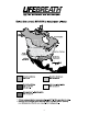
Table of Contents Caution Introduction .........................................................................2 Warranty..............................................................................2 ERV Questions & Answers .................................................3 Climate Map ........................................................................4 Technical Data - Model 95MAX ..........................................5 Technical Data - Model 155MAX ........................................
ERV Questions and Answers and damp situation. In fact, about 2/3 of the energy used by the air conditioner system is to remove moisture. Therefore, when ventilating in the summer, less moisture brought into the home means less work for the air conditioner, and energy savings for you. What is the difference between an HRV and an ERV? The core in an HRV (Heat Recovery Ventilator) transfers heat from one air stream to the other. This is called sensible heat.
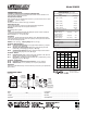
Model 95MAX ENGINEERING DATA OPTIONAL MAIN CONTROLS 99-350 Lifestyle Ventilation Control 7/24 programmable ventilation, (3 wire) 20 gauge wire (min.) 100’ length 99-109 Air Sentry Air Quality Monitor designed to accept remotely mounted Control Pad, (3 wire) 20 gauge wire (min.) 100’ length 99-250 Ventilation Dehumidistat designed to accept remotely mounted Control Pad, (4 wire) 20 gauge wire (min.
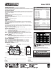
Model 155MAX ENGINEERING DATA OPTIONAL MAIN CONTROLS 99-350 Lifestyle Ventilation Control 7/24 programmable ventilation, (3 wire) 20 gauge wire (min.) 100’ length 99-109 Air Sentry Air Quality Monitor designed to accept remotely mounted Control Pad, (3 wire) 20 gauge wire (min.) 100’ length 99-250 Ventilation Dehumidistat designed to accept remotely mounted Control Pad, (4 wire) 20 gauge wire (min.
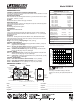
Model 155ECM ENGINEERING DATA OPTIONAL MAIN CONTROLS 99-350 Lifestyle Ventilation Control 7/24 programmable ventilation, (3 wire) 20 gauge wire (min.) 100’ length 99-109 Air Sentry Air Quality Monitor designed to accept remotely mounted Control Pad, (3 wire) 20 gauge wire (min.) 100’ length 99-250 Ventilation Dehumidistat designed to accept remotely mounted Control Pad, (4 wire) 20 gauge wire (min.
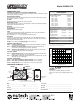
Model 155MAX RX ENGINEERING DATA OPTIONAL MAIN CONTROLS 99-350 Lifestyle Ventilation Control 7/24 programmable ventilation, (3 wire) 20 gauge wire (min.) 100’ length 99-109 Air Sentry Air Quality Monitor designed to accept remotely mounted Control Pad, (3 wire) 20 gauge wire (min.) 100’ length 99-250 Ventilation Dehumidistat designed to accept remotely mounted Control Pad, (4 wire) 20 gauge wire (min.
Model 200MAX ENGINEERING DATA OPTIONAL MAIN CONTROLS 99-350 Lifestyle Ventilation Control 7/24 programmable ventilation, (3 wire) 20 gauge wire (min.) 100’ length 99-109 Air Sentry Air Quality Monitor designed to accept remotely mounted Control Pad, (3 wire) 20 gauge wire (min.) 100’ length 99-250 Ventilation Dehumidistat designed to accept remotely mounted Control Pad, (4 wire) 20 gauge wire (min.
Model 200MAX RX ENGINEERING DATA OPTIONAL MAIN CONTROLS 99-350 Lifestyle Ventilation Control 7/24 programmable ventilation, (3 wire) 20 gauge wire (min.) 100’ length 99-109 Air Sentry Air Quality Monitor designed to accept remotely mounted Control Pad, (3 wire) 20 gauge wire (min.) 100’ length 99-250 Ventilation Dehumidistat designed to accept remotely mounted Control Pad, (4 wire) 20 gauge wire (min.
Model MAXTOP ENGINEERING DATA OPTIONAL MAIN CONTROLS 99-350 Lifestyle Ventilation Control 7/24 programmable ventilation, (3 wire) 20 gauge wire (min.) 100’ length 99-109 Air Sentry Air Quality Monitor designed to accept remotely mounted Control Pad, (3 wire) 20 gauge wire (min.) 100’ length 99-250 Ventilation Dehumidistat designed to accept remotely mounted Control Pad, (4 wire) 20 gauge wire (min.
Model 195DCS ENGINEERING DATA OPTIONAL MAIN CONTROLS 99-350 Lifestyle Ventilation Control 7/24 programmable ventilation, (3 wire) 20 gauge wire (min.) 100’ length 99-109 Air Sentry Air Quality Monitor designed to accept remotely mounted Control Pad, (3 wire) 20 gauge wire (min.) 100’ length 99-250 Ventilation Dehumidistat designed to accept remotely mounted Control Pad, (4 wire) 20 gauge wire (min.
Model 300DCS ENGINEERING DATA Performance (HVI certified) OPTIONAL MAIN CONTROLS 99-350 Lifestyle Ventilation Control 7/24 programmable ventilation, (3 wire) 20 gauge wire (min.) 100’ length 99-109 Air Sentry Air Quality Monitor designed to accept remotely mounted Control Pad, (3 wire) 20 gauge wire (min.) 100’ length 99-250 Ventilation Dehumidistat designed to accept remotely mounted Control Pad, (4 wire) 20 gauge wire (min.
Model 200ERV ENGINEERING DATA OPTIONAL MAIN CONTROLS 99-350 Lifestyle Ventilation Control 7/24 programmable ventilation, (3 wire) 20 gauge wire (min.) 100’ length 99-109 Air Sentry Air Quality Monitor designed to accept remotely mounted Control Pad, (3 wire) 20 gauge wire (min.) 100’ length 99-250 Ventilation Dehumidistat designed to accept remotely mounted Control Pad, (4 wire) 20 gauge wire (min.
Model 200ERVD ENGINEERING DATA OPTIONAL MAIN CONTROLS 99-350 Lifestyle Ventilation Control 7/24 programmable ventilation, (3 wire) 20 gauge wire (min.) 100’ length 99-109 Air Sentry Air Quality Monitor designed to accept remotely mounted Control Pad, (3 wire) 20 gauge wire (min.) 100’ length 99-250 Ventilation Dehumidistat designed to accept remotely mounted Control Pad, (4 wire) 20 gauge wire (min.
Function and Controls Self Test Each time the HRV/ERV is powered/energized the self test function will automatically initiate. During the self test the HRV/ERV will cycle through all the speeds available (1-5), test the damper motor operation and will default back to the previous mode/speed selection, (factory default is Speed 1). Total self test duration is approximately 1 min. 30 sec. Operating the ControlAir 15 Plugging in the HRV/ERV energizes the unit.
To Select Mode of Operation for ControlAir 15 Press and hold the fan selection button on the Control Pad. After 5 seconds the control will begin to cycle each mode holding each for 2 seconds. Release the button when the desired mode of operation is reached. Modes of Operation LED Indication OFF No LED’s illuminated HRV/ERV is off, no controls will initiate operation. ON/STANDBY Steady Green LED and Yellow LED to indicate speed HRV/ERV will run at speed selected in ventilation mode.
The Control Pad Mounted in the Control Module YEL Speed Indicator Lights RED ORG GRN Speed 5 - flashing yellow Speed 4 - solid yellow Speed 3 - solid yellow Speed 2 - solid yellow Speed 1 - solid yellow Mode Indicator Light BLK OFF..........................no light ON/STANDBY...........solid green 20 ON/40 OFF..........flashing green RECIRCULATION* ...solid red 20 ON/40 RECIRCULATE* .................................flashing orange AUTO DEFROST......
ControlAir-15 Optional Remote Controls Optional Main Controls ATTENTION The amount of ventilation required in your home will fluctuate according to the activity level in the house. Higher activity levels require more ventilation. Only one main control can be installed on your system. Main controls can be mounted in a central location of the home (i.e. beside the furnace thermostat) which will provide the user with complete control over their ventilation system from a convenient location.
Using the Dehumidistat Some models have a built-in dehumidistat (an optional remote wall mount dehumidistat can be installed, see Optional Remote Controls), to control harmful, excess humidity during the heating season. The dehumidistat operates in % of RH (relative humidity) with 80 being high and 20 being low. The average person is comfortable between 30-50%. Auto Dehumidistat Disable The HRV/ERV is equipped with a temperature sensor* which will measure the outdoor temperature.
DIMENSIONS 95MAX knockout for side mounting of EXHAUST return port 6" round collar converted to oval 18.5" (470 mm) 24.5" (622 mm) inches (mm) Hanging straps (4) 18.
Installation Location The HRV/ERV must be located in a heated space where it will be possible to conveniently service the unit. Typically the HRV/ERV would be located in the mechanical room or an area close to the outside wall where the weatherhoods will be mounted. If a basement area is not convenient or does not exist, a utility or laundry room may be used.
Installing Air Ducts Twisting or folding the duct will severely restrict air flow. See below for the recommended connection of flexible insulated ducts to the the outside weatherhoods and the HRV/ERV. A well designed and installed ducting system will allow theHRV/ERV to operate at its maximum efficiency. Always try to keep duct runs as short and straight as possible.See Installation Diagrams for various installation options.
Supply Air Ducting Dampers and Grilles The use of balancing dampers and/or adjustable grilles to balance the flow rates into various rooms is recommended. We suggest TECHGRILLE™ air diffusers. In homes without a forced air furnace, fresh air should be supplied to all bedrooms and living areas, excluding bathrooms, kitchen and utility areas. It should be supplied from high wall or ceiling locations. Grilles that diffuse the air comfortably such as the Techgrille™ are recommended.
Installation Diagrams Example diagram only - duct configuration may change depending on model Partially Dedicated System ATTENTION Duct configuration may change depending on the model. See Specifications for your unit. DIRECT CONNECTION of the SUPPLY AIR STREAM to the FURNACE COLD AIR RETURN (Stale air drawn from key areas of home) EXHAUST AIR from various parts of home. i.e. bathrooms (if required), kitchens (if required). Return Air 3' min.
Installation Diagrams Example diagram only - duct configuration may change depending on model Simplified Installation Option 1 (Return/Return Method) ATTENTION Duct configuration may change depending on the model. See Specifications for your unit. RETURN AIR Note: Option 1 is the preferred / recommended method when doing a simplified installation. DIRECT CONNECTION of both the HRV/ERV SUPPLY AIR STREAM and EXHAUST AIR STREAM to the FURNACE COLD AIR RETURN 40" (1m) MINIMUM 3' min.
Installation Diagrams Example diagram only - duct configuration may change depending on model Simplified Installation Option 2 (Supply/Return Method) ATTENTION It may be necessary to form an elbow in the supply side ducting as shown Duct configuration may change depending on the model. See Specifications for your unit. DIRECT CONNECTION of both the HRV/ERV SUPPLY AIR STREAM and EXHAUST AIR STREAM to the FURNACE COLD AIR RETURN & SUPPLY AIR SIDE RETURN AIR 3' min. recommended 3' min.
Installation Diagrams Example diagram only - duct configuration may change depending on model Fully Dedicated System ATTENTION Duct configuration may change depending on the model. See Specifications for your unit. Please Note: It is the responsibility of the installer to ensure all ductwork is sized and installed as designed to ensure the system will perform as intended. All air movement devices have a performance curve.
Pitot Tube Air Flow Balancing It is necessary to have balanced air flows in an HRV/ERV. The volume of air brought in from the outside must equal the volume of air exhausted by the unit.
Air Flow Balancing using AccuFlow Gauge Part No. 99-170 Models 155MAX, 155ECM, 155MAX RX, 200MAX, 200MAX RX AccuFlow Gauge Kit 1 - Accu-Flow Balancing Gauge 2 - Connection Hoses 4 - Rubber Fittings 1 - Instruction Page Lifebreath Accu-Flow is designed to quickly and accurately balance the airflows on units equipped with balancing ports. Normally the HRV/ERV would be balanced on high speed.
Air Flow Balancing using the Door Ports Models 155MAX, 155ECM, 155MAX RX, 200MAX, 200MAX RX The door ports ( MODELS 155 & 200) are designed to quickly and measure the airflows for balancing. Step 8 Repeat steps 4 to 7 as required to confirm airflows. Normally the HRV would be balanced on high speed. If the HRV is connected to a forced air system, both systems should be set to run at the highest operational speed when balancing is performed.
Balancing Collar Instructions Push and turn with slotted screwdriver. Damper automatically locks when pressure is released. When connecting ductwork to the collar, take note where screws are located. Screws should be located no further than 1/2” from outside edge of collar, so as not to impede operation of the damper.
Maintenance Routine for HRV (for ERV, see following page) 1. Inspect Exterior Hoods at least once a month. Make sure exhaust and fresh air supply hoods are not blocked or restricted by leaves, grass, or snow. In winter, it is especially important to make sure snow is not blocking the hoods or that frost has not built up on the wire mesh (bird screen). 4. Motors - Maintenance Free 5. Drain (condensate) Line - Clean once a year Inspect drain line, drain spout and “P” trap for blockage, mould or kinks.
Maintenance Routine for ERV (for HRV, see previous page) 1. Inspect Exterior Hoods at least once a month Make sure exhaust and fresh air supply hoods are not blocked up or restricted by leaves, grass, or dirt. 5. Clean Duct Work if Required The duct work running to and from the ERV may accumulate dirt. Wipe and vacuum the duct once every year. You may wish to contact a Heating/ Ventilation company to do this. WARNING: Blockage of hoods may cause an imbalance. 2.
Troubleshooting your HRV/ERV System SYMPTOM CAUSE SOLUTION Poor Air Flows • 1/4” (6 mm) mesh on the outside hoods is plugged • filters plugged • core obstructed • house grilles closed or blocked • dampers are closed if installed • poor power supply at site • ductwork is restricting HRV/ERV • improper speed control setting • HRV/ERV airflow improperly balanced • clean exterior hoods or vents • remove and clean filter • remove and clean core • check and open grilles • open and adjust dampers • have elec
Interlocking HRV Operation to an Airhandler/Furnace Blower - ControlAir 15 Electronics Connecting the HRV/ERV as illustrated will ensure the Air Handler/Furnace Blower Motor is operating whenever the HRV/ERV is ventilating. CAUTION Consideration must be given to competing airflows when connecting the HRV/ERV in conjunction with an Air Handler/Furnace Blower system.
Residential Wiring Diagram For All Models Except 155ECM RESIDENTIAL WIRING DIAGRAM MICRO PROCESSOR BOARD P4 TO DISABLE RECIRCULATION REMOVE SEL2 THERMIST0R (NOT ON ALL UNITS) P2 INTERNAL DEHUMIDISTAT SEL2 Note: All control connections are labeled by colour. Connect to corresponding colour with low voltage wire ( 20 gauge minimum).
Residential Wiring Diagram 155ECM LEGEND RESIDENTIAL WIRING DIAGRAM HIGH VOLTAGE 12V LOW VOLTAGE FIELD INSTALLED 12V LOW VOLTAGE MICRO PROCESSOR BOARD IMPORTANT: Control Low Voltage is 12VAC DO NOT CONNECT EXTERNAL POWER SOURCES TO UNIT P4 TO DISABLE RECIRCULATION REMOVE SEL2 THERMIST0R (NOT ON ALL UNITS) P2 INTERNAL DEHUMIDISTAT SEL2 YEL P5 REMOVE SEL1 FOR R-2000 GRN SEL1 DRY CONTACT WARNING 750 ma MAX FUSE ORN T1 N/C RED T2 COMMON BLK T6 N/O SEE DEFROST DETAIL P1 LINE CONTROLA