
Instruction manual

NOTE: Read the entire instruction manual before starting the
installation.
This symbol → indicates a change since the last issue.
INDEX
Page
SAFETY CONSIDERATIONS.....................................................1
INTRODUCTION..........................................................................1
INSTALLATION CONSIDERATIONS.......................................1
INSTALLATION........................................................................1-7
Thermidistat Control Location..............................................1-2
Set DIP Switches ......................................................................2
Install Thermidistat Control ..................................................2-3
Set Thermidistat Control Configuration ...............................3-6
System Start-Up and Checkout.............................................6-7
Final Settings ............................................................................7
HUMIDITY CONTROL FEATURES.....................................7-10
Humidification.......................................................................7-8
Dehumidification ...................................................................8-9
Vacation...............................................................................9-10
OPERATIONAL INFORMATION........................................10-19
WIRING DIAGRAMS ...........................................................11-19
THERMIDISTAT CONTROL TROUBLESHOOTING ............19
SAFETY CONSIDERATIONS
Read and follow manufacturer instructions carefully. Follow all
local electrical codes during installation. All wiring must conform
to local and national electrical codes. Improper wiring or installa-
tion may damage Thermidistat Control.
Recognize safety information. This is the safety-alert symbol
.
When you see this symbol on the equipment and in the instruction
manual, be alert to the potential for personal injury.
Understand the signal words DANGER, WARNING, and CAU-
TION. These words are used with the safety-alert symbol. DAN-
GER identifies the most serious hazards which will result in severe
personal injury or death. WARNING signifies a hazard which
could result in personal injury or death. CAUTION is used to
identify unsafe practices which would result in minor personal
injury or product and property damage.
INTRODUCTION
Bryant’s 7-day programmable Thermidistat Control is a wall-
mounted, low-voltage control which combines temperature and
humidity control in a single attractive unit. An extension of
Bryant’s proven line of thermostats, it provides separate set points
for heating and cooling, and now adds humidification and dehu-
midification. Different heating and cooling set points and times are
programmable for 4 periods per day and 7 days per week. The
Thermidistat Control can also be field-configured as a non-
programmable thermostat. When operating in the non-
programmable configuration it will still have both temperature and
humidity control. Humidify and dehumidify outputs provide direct
control of humidity. Batteries are not used. During power loss an
internal memory stores programs and settings for unlimited time,
and the clock continues to run for at least 8 hr.
INSTALLATION CONSIDERATIONS
A. Power
Note that this control does not require batteries and is not "power
stealing." It does require 24vac (R and C terminals) of the
low-voltage transformer to be connected to it for proper operation.
It will not operate without these 2 connections.
B. Models
There is a single programmable/non-programmable model for all
applications. It can be configured for AC or HP, 1- or 2-speed
compressor, and for dual fuel installations, allowing it to be used
in place of all Bryant thermostats.
C. Humidify Equipment and Connections
The humidify output connects directly to 24vac operated humidi-
fiers. No other connection or interlock is required. Any of several
installer-selectable operating modes are available.
D. Dehumidify Equipment and Connections
The dehumidify output connects to the dehumidify input on
variable-speed furnaces and fan coils. Additional dehumidification
is done by controlling the compressor. A variety of operating
modes are available.
E. Outdoor Temperature Sensor
Optimum performance is obtained when an outdoor temperature
sensor is used with the Thermidistat Control. Plan installation so
that 2 wires can be run from Thermidistat Control to an outdoor
location, preferably on the north side of the house or refer to
Installation Instructions included with the outdoor temperature
sensor for simplified connection. Sensor can be mounted to
outdoor unit and existing control wires may be used for its
connection. Details are provided in sensor instructions.
INSTALLATION
I. THERMIDISTAT CONTROL LOCATION
Thermidistat Control should be mounted:
• Approximately 5 ft (1.5m) from floor.
• Close to or in a frequently used room, preferably on an inside
partitioning wall.
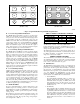
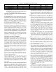
Fig. 1—Thermidistat Control
HEIGHT (IN.) WIDTH (IN.) DEPTH (IN.)
4-1/4 7-1/2 1-3/8
A96373
®
installation and
start-up instructions
THERMIDISTAT™ CONTROL
Cancels: II TSTAT-0-16 II TSTAT-0-20
5-98
TSTAT
—1—
→