558J SINGLE PACKAGE ROOFTOP COOLING UNIT 3 TO 6 NOMINAL TONS Product Data the environmentally sound refrigerant This product has been designed and manufactured to meet Energy Star® criteria for energy efficiency. However, proper refrigerant charge and proper air flow are critical to achieve rated capacity and efficiency. Installation of this product should follow all manufacturer’s refrigerant charging and air flow instructions.
TABLE OF CONTENTS PAGE FEATURES AND BENEFITS . . . . . . . . . . . . . . . . . . . . 3 COOLING TABLES . . . . . . . . . . . . . . . . . . . . . . . . . . . 20 MODEL NUMBER NOMENCLATURE . . . . . . . . . . . . 4 STATIC PRESSURE TABLES . . . . . . . . . . . . . . . . . . . 24 FACTORY OPTIONS & ACCESSORIES . . . . . . . . . . . 5 FAN PERFORMANCE . . . . . . . . . . . . . . . . . . . . . . . . . 25 ARI CAPACITY RATING . . . . . . . . . . . . . . . . . . . . . . . 8 OUTDOOR AIR INTAKE & EXHAUST PERF . .
FEATURES AND BENEFITS S Up to 28% lighter than similar industry units. Lighter rooftops make easier replacement jobs. S 3-- 6 ton units fit on existing Bryant small rooftop curb. This saves time and money on replacement jobs. S Standardized components and layout. Standardized components and controls make service and stocking parts easier. S Scroll compressors on all units. This makes service, stocking parts, replacement, and trouble-- shooting easier. S Field convertible airflow (3-- 6 tons).
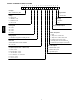
MODEL NUMBER NOMENCLATURE 1 2 3 4 5 5 8 J E 0 ____________ 5 6 7 8 9 6 A 0 ______ 10 11 12 13 14 15 16 17 18 0 0 A 1 A 0 A A A ________ ______ Unit Type 558J = Std Efficiency RTU Design Revision Voltage A = First Revision E = 460--- 3--- 60 J = 208/230--- 1--- 60 Packaging P = 208/230--- 3--- 60 A = Standard T = 575--- 3--- 60 B = LTL 558J Cooling Tons Factory Installed Options 04 = 3 Ton 05 = 4 Ton 06 = 5 Ton Outdoor Air Options 07 = 6 Ton A = None Refrig.
Table 1 – FACTORY--INSTALLED OPTIONS AND FIELD--INSTALLED ACCESSORIES Cabinet Coil Options Condenser Protection Controls Economizers & Outdoor Air Dampers Economizer Sensors & IAQ Devices Indoor Motor & Drive Low Ambient Control Power Options Roof Curbs ITEM Thru ---the ---base electrical connections Cu/Cu indoor and/or outdoor coils Pre ---coated outdoor coils Premium, E ---coated outdoor coils Condenser coil hail guard (louvered design) Condenser coil hail guard (hood design) Thermostats, temperatur
558J FACTORY OPTIONS AND/OR ACCESSORIES Economizer (dry--bulb or enthalpy) RTU--MP, Multi--protocol Controller Economizers save money. They bring in fresh, outside air for ventilation; and provide cool, outside air to cool your building. This is the preferred method of low-- ambient cooling. When coupled to CO2 sensors, Economizers can provide even more savings by coupling the ventilation air to only that amount required.
Alternate Motors and Drives Some applications need larger horsepower motors, some need more airflow, and some need both. Regardless of the case, Bryant has a factory installed combination to meet your application. A wide selection of motors and pulleys (drives) are available, factory installed, to handle nearly any application.
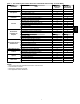
Table 2 – ARI COOLING RATING TABLES UNIT 04 05 06 07 NOM. CAPACITY (TONS) 3 4 5 6 NET COOLING CAPACITY (KBTU / HR) 34.6 45.0 59.0 70.0 TOTAL POWER (KW) SEER EER IPLV IEER 3.1 4.0 5.5 6.4 13.0 13.0 13.0 N/A 11.0 11.0 10.8 11.0 N/A N/A N/A N/A N/A N/A N/A 11.4 558J LEGEND ARI --- Air ---Conditioning & Refrigeration Institute ASHRAE --- American Society of Heating, Refrigerating and Air Conditioning, Inc.
Table 3 – MINIMUM -- MAXIMUM AIRFLOWS ELECTRIC HEAT 04 05 06 07 COOLING Minimum 900 1200 1500 1800 Maximum 1500 2000 2500 3000 ELECTRIC HEATERS Minimum Maximum 900 1500 1200 2000 1500 2500 1800 3000 558J UNIT 9
Table 4 – SOUND PERFORMANCE TABLE UNIT 04 05 06 07 A ---Weighted 80 81 78 78 558J LEGEND dB --- Decibel 63 90.6 90.9 84.0 88.8 125 80.9 84.6 82.2 81.8 OUTDOOR SOUND (dB) 250 500 1000 80.2 76.0 74.6 79.5 77.9 76.5 76.3 74.8 72.5 76.9 74.4 73.3 2000 71.3 71.1 68.8 69.8 4000 68.5 66.9 65.6 66.3 8000 63.9 62.5 61.8 62.7 NOTES: 1. Outdoor sound data is measure in accordance with ARI standard 270---95. 2. Measurements are expressed in terms of sound power.
558J*06 558J*07 1 / 1 / Scroll 5.6 25 Acutrol 630 / 505 54 / 117 1 / 1 / Scroll 8.5 42 Acutrol 630 / 505 54 / 117 1 / 1 / Scroll 10.7 42 Acutrol 630 / 505 54 / 117 1 / 1 / Scroll 14.1 56 Acutrol 630 / 505 54 / 117 Cu / Al 3/8” RTPF 2 / 15 5.5 3/4” Cu / Al 3/8” RTPF 2 / 15 5.5 3/4” Cu / Al 3/8” RTPF 4 / 15 5.5 3/4” Cu / Al 3/8” RTPF 4 / 15 7.3 3/4” Standard Static 1 phase Motor Qty / Drive Type Max BHP RPM Range Motor Frame Size Fan Qty / Type Fan Diameter (in) 1 / Belt 1.
IFM TYPE STD MED MED HIGH 460--- 3--- 60 STD HIGH 208/230--- 3--- 60 558J*04 STD MED V ---PH ---HZ 558J 208/230--- 1--- 60 UNIT Table 6 – ELECTRIC HEAT -- ELECTRICAL DATA LEGEND: CO --DISC FLA IFM LRA MCA MOCP PE UNPWRD CO ELECTRIC HEATER PART NUMBER CRHEATERXXXXXX NOMINAL POWER (kW) APPLICATION POWER (kW) 101A00 102A00 103B00 104B00 102A00,102A00 101A00 102A00 103B00 104B00 102A00,102A00 101A00 102A00 103B00 104B00 105A00 101A00 102A00 103B00 104B00 105A00 101A00 102A00 103B00 104B00 105A0
LEGEND: CO --DISC FLA IFM LRA MCA MOCP PE UNPWRD CO ELECTRIC HEATER PART NUMBER CRHEATERXXXXXX NOMINAL POWER (kW) APPLICATION POWER (kW) 101A00 103B00 102A00,102A00 103B00,103B00 104B00,104B00 101A00 103B00 102A00,102A00 103B00,103B00 104B00,104B00 102A00 103B00 105A00 104B00,104B00 102A00 103B00 105A00 104B00,104B00 102A00 103B00 105A00 104B00,104B00 106A00 108A00 109A00 108A00,108A00 106A00 108A00 109A00 108A00,108A00 106A00 108A00 109A00 108A00,108A00 4.4 8.7 13.0 17.4 21.0 4.4 8.7 13.0 17.4 21.0 6.
IFM TYPE STD MED MED HIGH 460--- 3--- 60 STD HIGH 208/230--- 3--- 60 558J*06 558J STD MED V ---PH ---HZ 208/230--- 1--- 60 UNIT Table 6 -- ELECTRIC HEAT -- ELECTRICAL DATA LEGEND: CO --DISC FLA IFM LRA MCA MOCP PE UNPWRD CO ELECTRIC HEATER PART NUMBER CRHEATERXXXXXX NOMINAL POWER (kW) APPLICATION POWER (kW) 102A00 103B00 102A00,102A00 103B00,103B00 104B00,104B00 102A00 103B00 102A00,102A00 103B00,103B00 104B00,104B00 102A00 104B00 105A00 104B00,104B00 104B00,105A00 102A00 104B00 105A00 104B0
LEGEND: CO --DISC FLA IFM LRA MCA MOCP PE UNPWRD CO ELECTRIC HEATER PART NUMBER CRHEATERXXXXXX NOMINAL POWER (kW) APPLICATION POWER (kW) 102A00 104B00 105A00 104B00,104B00 104B00,105A00 102A00 104B00 105A00 104B00,104B00 104B00,105A00 102A00 104B00 105A00 104B00,104B00 104B00,105A00 106A00 108A00 109A00 108A00,108A00 108A00,109A00 106A00 108A00 109A00 108A00,108A00 108A00,109A00 106A00 108A00 109A00 108A00,108A00 108A00,109A00 6.5 10.5 16.0 21.0 26.5 6.5 10.5 16.0 21.0 26.5 6.5 10.5 16.0 21.0 26.5 6.
CURBS & WEIGHTS DIMENSIONS -- CHASSIS 1 Corner A Corner D Corner B Corner C 7” 558J 6 1/8” 11 3/8” 10 1/2” 19 1/2” 16 1/4” 22” C08001 21 1/4” J 19 1/2” 6 5/8” 33 3/8” 4 5/8” 16” K 74 3/8” C08000 Table 7 – BASE UNIT DIMENSIONS -- CHASSIS 1 UNIT 04 05 06 07 OPERATING WGT (LB) 438 494 524 607 SHIPPING WGT (LB) 475 530 560 645 J 33 5/16” 33 5/16” 33 5/16” 41 5/16” A 108 122 130 150 CORNER WEIGHTS (LB) B C 115 110 130 125 138 132 160 153 NOTES: 1.
GASKET (SUPPLIED WITH CURB) 1 NAIL 18” (457) COUNTER FLASHING (FIELD SUPPLIED) ROOFING FELT (FIELD SUPPLIED) CANT STRIP (FIELD SUPPLIED) ROOFING FELT (FIELD SUPPLIED) 42" (1067) 18" (457) 42" (1067) 1 Required bottom condensate drain connection. Otherwise, 36” (914mm) for condensate connection. C07457 C07459 Fig. 2 -- Service Clearance 558J Fig. 1 -- Curb Installation Detail (Typical) C07458 Fig. 3 -- Curb Dimensions C07461 Fig.
APPLICATION DATA Min operating ambient temp (cooling): Sizing a rooftop In mechanical cooling mode, your Bryant rooftop can safely operate down to an outdoor ambient temperature of 25_F (-- 4_C), with an accessory winter start kit. It is possible to provide cooling at lower outdoor ambient temperatures by using less outside air, economizers, and/or accessory low ambient kits. Bigger isn’t necessarily better.
SELECTION PROCEDURE (WITH 558J*07 EXAMPLE) II. Determine cooling and heating loads. Given: Mixed Air Drybulb 80_F (27_C) Mixed Air Wetbulb 67_F (19_C) Ambient Drybulb 95_F (35_C) 69.0 MBH THCLoad 51.0 MBH SHCLoad Supply Air 2100 CFM Heating Load 85.0 MBH External Static Pressure 0.67 in.wg Electrical Characteristics 230-- 3-- 60 Make an initial guess at cooling tons. Refrig. tons = THCLoad / 12 MBH per ton Refrig. tons = 69.0 / 12 = 5.75 tons In this case, start by looking at the 558J*07. III.
Table 8 – COOLING CAPACITIES 558J*04 58 EAT (wB) 900 Cfm 62 67 72 76 558J 58 EAT (wB) 1050 Cfm 62 67 72 76 58 EAT (wB) 1200 Cfm 62 67 72 76 58 EAT (wB) 1350 Cfm 62 67 72 76 58 EAT (wB) 1500 Cfm 62 67 72 76 LEGEND: --Cfm EAT(db) EAT(wb) N/A SHC THC --------------- THC SHC THC SHC THC SHC THC SHC THC SHC THC SHC THC SHC THC SHC THC SHC THC SHC THC SHC THC SHC THC SHC THC SHC THC SHC THC SHC THC SHC THC SHC THC SHC THC SHC THC SHC THC SHC THC SHC THC SHC THC SHC 75 28.1 24.4 30.3 22.6 35.
558J*05 58 EAT (wB) 1200 Cfm 62 67 72 76 58 EAT (wB) 1400 cfm 62 67 72 76 58 EAT (wB) 1600 Cfm 62 67 72 76 58 EAT (wB) 1800 Cfm 62 67 72 76 58 EAT (wB) 2000 Cfm 62 67 72 76 LEGEND: --Cfm EAT(db) EAT(wb) N/A SHC THC --------------- THC SHC THC SHC THC SHC THC SHC THC SHC THC SHC THC SHC THC SHC THC SHC THC SHC THC SHC THC SHC THC SHC THC SHC THC SHC THC SHC THC SHC THC SHC THC SHC THC SHC THC SHC THC SHC THC SHC THC SHC THC SHC 75 ----43.1 31.2 47.4 25.9 51.1 20.1 ----41.9 36.6 44.6 33.
Table 10 – COOLING CAPACITIES 558J*06 58 EAT (wB) 1500 Cfm 62 67 72 76 558J 58 EAT (wB) 1750 Cfm 62 67 72 76 58 EAT (wB) 2000 Cfm 62 67 72 76 58 EAT (wB) 2250 Cfm 62 67 72 76 58 EAT (wB) 2500 Cfm 62 67 72 76 LEGEND: --Cfm EAT(db) EAT(wb) N/A SHC THC --------------- THC SHC THC SHC THC SHC THC SHC THC SHC THC SHC THC SHC THC SHC THC SHC THC SHC THC SHC THC SHC THC SHC THC SHC THC SHC THC SHC THC SHC THC SHC THC SHC THC SHC THC SHC THC SHC THC SHC THC SHC THC SHC 75 52.9 45.8 56.2 41.
558J*07 58 EAT (wB) 1800 Cfm 62 67 72 76 58 EAT (wB) 2100 Cfm 62 67 72 76 58 EAT (wB) 2400 Cfm 62 67 72 76 58 EAT (wB) 2700 Cfm 62 67 72 76 58 EAT (wB) 3000 Cfm 62 67 72 76 LEGEND: --Cfm EAT(db) EAT(wb) N/A SHC THC --------------- THC SHC THC SHC THC SHC THC SHC THC SHC THC SHC THC SHC THC SHC THC SHC THC SHC THC SHC THC SHC THC SHC THC SHC THC SHC THC SHC THC SHC THC SHC THC SHC THC SHC THC SHC THC SHC THC SHC THC SHC THC SHC 75 64.9 56.6 68.7 51.7 75.6 42.8 82.6 33.5 ----68.9 60.1 70.
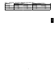
Table 12 – STATIC PRESSURE ADDERS (Factory Options and/or Accessories) CFM Vertical Economizer Horizontal Economizer CFM 1 Electric Heater Module 2 Electric Heater Modules 600 0.01 --- 800 0.02 --- 600 0.03 0.14 900 0.05 0.15 1000 0.035 --- 1200 0.07 0.16 1250 0.045 --- 1500 0.065 --- 1400 0.09 0.16 1750 0.08 0.1 1600 0.09 0.16 2000 0.12 0.125 1800 0.1 0.17 2250 0.145 0.15 2000 0.11 0.17 2500 0.175 0.18 2200 0.11 0.17 2750 0.22 0.225 2400 0.12 0.18 3000 0.255 0.275 2600 0.13 0.
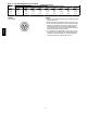
FAN PERFORMANCE CFM 900 975 1050 1125 1200 1275 1350 1425 1500 CFM 900 975 1050 1125 1200 1275 1350 1425 1500 1 PHASE 0.2 RPM BHP Field---Supplied Drive1 554 0.14 575 0.16 597 0.18 620 0.21 643 0.23 666 0.27 690 0.30 714 0.34 738 0.38 1.2 RPM BHP 1017 1035 1053 1071 1089 1107 1126 1145 1164 0.64 0.68 0.73 0.78 0.84 0.90 0.96 1.03 1.10 RPM 681 701 721 741 762 784 805 827 849 3 TON HORIZONTAL SUPPLY AVAILABLE EXTERNAL STATIC PRESSURE (IN. WG) 0.4 0.6 0.8 1.
FAN PERFORMANCE (cont.) Table 15 – 558J*04 CFM 558J 900 975 1050 1125 1200 1275 1350 1425 1500 CFM 900 975 1050 1125 1200 1275 1350 1425 1500 3 PHASE 0.2 RPM BHP Field---Supplied Drive1 554 0.14 575 0.16 597 0.18 620 0.21 643 0.23 666 0.27 690 0.30 714 0.34 738 0.38 1.2 RPM BHP 1017 1035 1053 1071 1089 1107 1126 1145 1164 0.64 0.68 0.73 0.78 0.84 0.90 0.96 1.03 1.10 RPM 681 701 721 741 762 784 805 827 849 3 TON HORIZONTAL SUPPLY AVAILABLE EXTERNAL STATIC PRESSURE (IN. WG) 0.4 0.6 0.8 1.
FAN PERFORMANCE (cont.) CFM 1200 1300 1400 1500 1600 1700 1800 1900 2000 CFM 1200 1300 1400 1500 1600 1700 1800 1900 2000 1 PHASE 4 TON HORIZONTAL SUPPLY AVAILABLE EXTERNAL STATIC PRESSURE (IN. WG) 0.4 0.6 0.8 BHP RPM BHP RPM BHP RPM BHP Standard Static Option Medium Static Option 0.23 762 0.35 860 0.46 944 0.58 0.28 791 0.40 887 0.52 970 0.65 0.33 820 0.45 914 0.59 997 0.72 0.38 849 0.52 942 0.66 1024 0.80 0.44 879 0.59 971 0.74 1051 0.89 0.51 910 0.66 1000 0.82 1079 0.98 0.59 941 0.75 1029 0.
FAN PERFORMANCE (cont.) Table 19 – 558J*05 CFM 558J 1200 1300 1400 1500 1600 1700 1800 1900 2000 CFM 1200 1300 1400 1500 1600 1700 1800 1900 2000 3 PHASE 4 TON HORIZONTAL SUPPLY AVAILABLE EXTERNAL STATIC PRESSURE (IN. WG) 0.4 0.6 0.8 BHP RPM BHP RPM BHP RPM BHP Standard Static Option Medium Static Option 0.23 762 0.35 860 0.46 944 0.58 0.28 791 0.40 887 0.52 970 0.65 0.33 820 0.45 914 0.59 997 0.72 0.38 849 0.52 942 0.66 1024 0.80 0.44 879 0.59 971 0.74 1051 0.89 0.51 910 0.66 1000 0.82 1079 0.98 0.
FAN PERFORMANCE (cont.) CFM 1500 1625 1750 1875 2000 2125 2250 2375 2500 CFM 1500 1625 1750 1875 2000 2125 2250 2375 2500 1 PHASE 0.2 0.4 RPM BHP Field---Supplied Drive1 724 0.33 765 0.40 806 0.48 849 0.57 892 0.67 935 0.79 980 0.92 1024 1.06 1069 1.22 1.2 RPM BHP 1188 1213 1239 1267 ----------- 1.09 1.18 1.28 1.40 ----------- RPM 837 873 909 947 986 1025 1066 1107 1149 5 TON HORIZONTAL SUPPLY Available External Static Pressure (in. wg) 0.6 0.8 BHP RPM BHP RPM Standard Static Option 0.45 937 0.
FAN PERFORMANCE (cont.) Table 23 – 558J*06 CFM 0.2 CFM 1500 1625 1750 1875 2000 2125 2250 2375 2500 0.4 RPM BHP Field---Supplied Drive1 724 0.33 765 0.40 806 0.48 849 0.57 892 0.67 935 0.79 980 0.92 1024 1.06 1069 1.22 558J 1500 1625 1750 1875 2000 2125 2250 2375 2500 3 PHASE RPM 837 873 909 947 986 1025 1066 1107 1149 1.2 RPM BHP RPM 1188 1213 1239 1267 1296 1326 1358 1390 1424 1.09 1.18 1.28 1.40 1.53 1.67 1.83 2.00 2.
FAN PERFORMANCE (cont.) CFM 1800 1950 2100 2250 2400 2550 2700 2850 3000 3 PHASE 0.2 RPM BHP Field---Supplied Drive1 822 0.51 872 0.62 923 0.75 974 0.90 1026 1.06 1079 1.25 1132 1.46 1186 1.69 1240 1.94 6 TON HORIZONTAL SUPPLY AVAILABLE EXTERNAL STATIC PRESSURE (IN. WG) 0.4 0.6 0.8 RPM BHP RPM BHP RPM BHP 927 973 1019 1067 1115 1164 1214 1264 1315 0.66 0.79 0.92 1.08 1.26 1.46 1.67 1.92 2.18 BHP 0.98 1.13 1.29 1.46 1.66 1.88 2.12 2.39 2.68 1174 1213 1253 1294 1336 1379 1422 1467 1512 1.15 1.
FAN PERFORMANCE (cont.) Table 27 – PULLEY ADJUSTMENT 1 phase 1 phase 3 phase 05 3 phase 3 phase 06 07 558J 3 phase 04 1 phase UNIT MOTOR/DRIVE COMBO 0.0 0.5 1.0 MOTOR PULLEY TURNS OPEN 1.5 2.0 2.5 3.0 3.5 4.0 4.5 5.
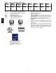
STATIC PRESSURE LOSSES (in. wg) ECONOMIZER, BAROMETRIC RELIEF AND PE PERFORMANCE STATIC PRESSURE LOSSES (in. wg) 0.3 0.2 3 - 6 Ton 0.1 0 0 500 1000 1500 2000 2500 0.5 0.4 0.3 3 - 6 Ton 0.2 0.1 0 5 0.3 3 - 6 Ton 0.2 0.1 0 20 25 30 0.35 0.3 0.25 0.2 3 - 6 Ton 0.15 0.1 0.05 0 0 1000 Fig. 10 -- Return Air Pressure Drop EXHAUST AIRFLOW (cfm) STATIC PRESSURE LOSSES (in. wg) 0.4 0.3 0.2 3 - 6 Ton 0.1 2500 2000 1500 1000 500 0 0 0.1 1000 2000 3000 4000 5000 6000 0.3 0.4 0.
ELECTRICAL INFORMATION 558J Table 28 – 558J*04 3 TONS V ---Ph---Hz VOLTAGE RANGE MIN MAX RLA LRA WATTS FLA 208--- 1--- 60 187 253 16.6 79 325 1.5 230--- 1--- 60 187 253 16.6 79 325 1.5 208--- 3--- 60 187 253 10.4 73 325 1.5 230--- 3--- 60 187 253 10.4 73 325 1.5 460--- 3--- 60 414 506 5.8 38 325 0.8 575--- 3--- 60 518 633 3.8 37 325 0.
ELECTRICAL INFORMATION (CONT) Table 30 – 558J*06 5 TONS RLA LRA WATTS FLA 208--- 1--- 60 187 253 26.2 134 325 1.5 230--- 1--- 60 187 253 26.2 134 325 1.5 208--- 3--- 60 187 253 15.6 110 325 1.5 230--- 3--- 60 187 253 15.6 110 325 1.5 460--- 3--- 60 414 506 7.7 52 325 0.8 575--- 3--- 60 518 633 5.8 39 325 0.
V ---PH ---HZ 558J 208/230--- 1--- 60 UNIT Table 32 – MCA/MOCP DETERMINATION NO C.O. OR UNPWRD C.O. ELECTRIC HEATER IFM TYPE FLA MCA MOCP --3.3/4.4 4.9/6.5 6.5/8.7 7.9/10.5 9.8/13.0 --3.3/4.4 4.9/6.5 6.5/8.7 7.9/10.5 9.8/13.0 --3.3/4.4 4.9/6.5 6.5/8.7 7.9/10.5 12.0/16.0 --3.3/4.4 4.9/6.5 6.5/8.7 7.9/10.5 12.0/16.0 --3.3/4.4 4.9/6.5 6.5/8.7 7.9/10.5 12.0/16.0 --6.0 8.8 11.5 14.0 --6.0 8.8 11.5 14.0 --6.0 8.8 11.5 14.0 --15.9/18.3 23.5/27.1 31.4/36.3 37.9/43.8 46.9/54.2 --15.9/18.3 23.5/27.1 31.4/36.
ELECTRIC HEATER IFM TYPE STD MED 208/230--- 3--- 60 558J*05 STD MED HIGH 460--- 3--- 60 STD MED 575--- 3--- 60 HIGH NO C.O. or UNPWRD C.O. NO P.E. kW FLA MCA MOCP --3.3/4.4 6.5/8.7 9.8/13.0 13.1/17.4 15.8/21.0 --3.3/4.4 6.5/8.7 9.8/13.0 13.1/17.4 15.8/21.0 --4.9/6.5 6.5/8.7 12.0/16.0 15.8/21.0 --4.9/6.5 6.5/8.7 12.0/16.0 15.8/21.0 --4.9/6.5 6.5/8.7 12.0/16.0 15.8/21.0 --6.0 11.5 14.0 23.0 --6.0 11.5 14.0 23.0 --6.0 11.5 14.0 23.0 --15.9/18.3 31.4/36.3 46.9/54.2 62.8/72.5 75.8/87.5 --15.
V ---PH ---HZ 208/230--- 1--- 60 UNIT Table 34 – MCA/MOCP DETERMINATION W/ PWRD C.O. ELECTRIC HEATER IFM TYPE kW FLA STD --4.9/6.5 6.5/8.7 9.8/13.0 13.1/17.4 15.8/21.0 --4.9/6.5 6.5/8.7 9.8/13.0 13.1/17.4 15.8/21.0 --4.9/6.5 7.9/10.5 12.0/16.0 15.8/21.0 19.9/26.5 --4.9/6.5 7.9/10.5 12.0/16.0 15.8/21.0 19.9/26.5 --4.9/6.5 7.9/10.5 12.0/16.0 15.8/21.0 19.9/26.5 --6.0 11.5 14.0 23.0 25.5 --6.0 11.5 14.0 23.0 25.5 --6.0 11.5 14.0 23.0 25.
ELECTRIC HEATER IFM TYPE kW FLA --4.9/6.5 7.9/10.5 12.0/16.0 15.8/21.0 19.9/26.5 --4.9/6.5 7.9/10.5 12.0/16.0 15.8/21.0 19.9/26.5 --4.9/6.5 7.9/10.5 12.0/16.0 15.8/21.0 19.9/26.5 --6.0 11.5 14.0 23.0 25.5 --6.0 11.5 14.0 23.0 25.5 --6.0 11.5 14.0 23.0 25.5 STD --13.6/15.6 21.9/25.3 33.4/38.5 43.8/50.5 55.2/63.8 --13.6/15.6 21.9/25.3 33.4/38.5 43.8/50.5 55.2/63.8 --13.6/15.6 21.9/25.3 33.4/38.5 43.8/50.5 55.2/63.8 --7.2 13.8 16.8 27.7 30.7 --7.2 13.8 16.8 27.7 30.7 --7.2 13.8 16.8 27.7 30.7 30.5 30.
V ---PH ---HZ 558J 208/230--- 1--- 60 UNIT Table 36 – MCA/MOCP DETERMINATION W/ PWRD C.O. ELECTRIC HEATER IFM TYPE 208/230--- 3--- 60 MCA MOCP w/ P.E. (pwrd fr/unit) DISC. SIZE LRA 100 100/100 100/100 100/100 100/100 100/100 100 100/100 100/100 100/100 100/100 100/100 94 94/94 94/94 94/94 94/94 94/94 94 94/94 94/94 94/94 94/94 94/94 112 112/112 112/112 112/112 112/112 112/112 48 48 48 48 48 48 48 48 48 48 57 57 57 57 57 MCA MOCP 33.9 34.4/37.4 43.9/48.4 53.8/59.9 61.9/69.3 73.1/82.3 33.9 34.4/37.
ELECTRIC HEATER IFM TYPE FLA MCA MOCP STD --4.9/6.5 6.5/8.7 9.8/13.0 13.1/17.4 15.8/21.0 --4.9/6.5 6.5/8.7 9.8/13.0 13.1/17.4 15.8/21.0 --4.9/6.5 7.9/10.5 12.0/16.0 15.8/21.0 19.9/26.5 --4.9/6.5 7.9/10.5 12.0/16.0 15.8/21.0 19.9/26.5 --4.9/6.5 7.9/10.5 12.0/16.0 15.8/21.0 19.9/26.5 --6.0 11.5 14.0 23.0 25.5 --6.0 11.5 14.0 23.0 25.5 --6.0 11.5 14.0 23.0 25.5 --- --23.5/27.1 31.4/36.3 46.9/54.2 62.8/72.5 75.8/87.5 --23.5/27.1 31.4/36.3 46.9/54.2 62.8/72.5 75.8/87.5 --13.6/15.6 21.9/25.3 33.4/38.5 43.
V ---PH ---HZ UNIT Table 38 – MCA/MOCP DETERMINATION W/ PWRD C.O. ELECTRIC HEATER IFM TYPE kW FLA --4.9/6.5 7.9/10.5 12.0/16.0 15.8/21.0 19.9/26.5 --4.9/6.5 7.9/10.5 12.0/16.0 15.8/21.0 19.9/26.5 --4.9/6.5 7.9/10.5 12.0/16.0 15.8/21.0 19.9/26.5 --6.0 11.5 14.0 23.0 25.5 --6.0 11.5 14.0 23.0 25.5 --6.0 11.5 14.0 23.0 25.5 STD --13.6/15.6 21.9/25.3 33.4/38.5 43.8/50.5 55.2/63.8 --13.6/15.6 21.9/25.3 33.4/38.5 43.8/50.5 55.2/63.8 --13.6/15.6 21.9/25.3 33.4/38.5 43.8/50.5 55.2/63.8 --7.2 13.8 16.8 27.
ELECTRIC HEATER IFM TYPE FLA MCA MOCP --3.3/4.4 6.5/8.7 9.8/13.0 13.1/17.4 15.8/21.0 --3.3/4.4 6.5/8.7 9.8/13.0 13.1/17.4 15.8/21.0 --4.9/6.5 6.5/8.7 12.0/16.0 15.8/21.0 --4.9/6.5 6.5/8.7 12.0/16.0 15.8/21.0 --4.9/6.5 6.5/8.7 12.0/16.0 15.8/21.0 --6.0 11.5 14.0 23.0 --6.0 11.5 14.0 23.0 --6.0 11.5 14.0 23.0 --15.9/18.3 31.4/36.3 46.9/54.2 62.8/72.5 75.8/87.5 --15.9/18.3 31.4/36.3 46.9/54.2 62.8/72.5 75.8/87.5 --13.6/15.6 18.1/20.9 33.4/38.5 43.8/50.5 --13.6/15.6 18.1/20.9 33.4/38.5 43.8/50.5 --13.6/15.
558J C08054 Fig.
558J NOTES: Terminal board schematic layout does not match actual terminal board to simplify circuit traces. Ensure designated jumpers on terminal board are cut when adding smoke detectors, phase loss relay and remote shutdown. ECONOMIZER NOTES: 1. 620 ohm, 1 watt, 5% resister should be removed only when using differential enthalpy or dry bulb. 2. If a separate field --- supplied 24V transformer is used for the IAQ sensor power supply, it cannot have the secondary of the transformer grounded. 3.
SEQUENCE OF OPERATION General The sequence below describes the sequence of operation for an electro-- mechanical unit with and without a factory installed EconoMi$er IV (called “economizer” in this sequence). For information regarding a direct digital controller, see the start-- up, operations, and troubleshooting manual for the applicable controller. Electro--mechanical units with no economizer 558J Cooling — When the thermostat calls for cooling, terminals G and Y1 are energized.
GUIDE SPECIFICATIONS -- 558J*04--07 Note about this specification: Bryant wrote this specification in the 2004 version of the “Masterformat” as published by the Construction Specification Institute. Please feel free to copy this specification directly into your building spec. HVAC Guide Specifications Size Range: 3 to 6 Nominal Tons 558J the environmentally sound refrigerant This product has been designed and manufactured to meet Energy Star® criteria for energy efficiency.
558J 7. Shall have an LED display independently showing the status of serial communication, running, errors, power, all digital outputs, and all analog inputs. 8. Shall accept the following inputs: Space temperature, Set point adjustment, Outdoor Air temperature, indoor Air quality, outdoor air quality, compressor lock-- out, fire shutdown, enthalpy switch, and fan status/filter status/ humidity/ remote occupancy. 9.
23 81 19.13 Small-- Capacity Self-- Contained Air Conditioners (558J*04-- 07) 23 81 19.13.A. General 1. Outdoor, rooftop mounted, electrically controlled, heating and cooling unit utilizing a(n) hermetic scroll compressor(s) for cooling duty and gas combustion for heating duty. 2. Factory assembled, single-- piece heating and cooling rooftop unit. Contained within the unit enclosure shall be all factory wiring, piping, controls, and special features required prior to field start-- up. 3.
558J 1. Unit cabinet shall be constructed of galvanized steel, and shall be bonderized and coated with a pre-- painted baked enamel finish on all externally exposed surfaces. 2. Unit cabinet exterior paint shall be: film thickness, (dry) 0.003 inches minimum, gloss (per ASTM D523, 60_F/16_C): 60, Hardness: H-- 2H Pencil hardness. 3. Evaporator fan compartment interior cabinet insulation shall conform to ARI Standards 210 or 360 minimum exterior sweat criteria.
558J 3. Optional Copper-- fin coils: a. Shall be constructed of copper fins mechanically bonded to copper tubes and copper tube sheets. b. Galvanized steel tube sheets shall not be acceptable. c. A polymer strip shall prevent coil assembly from contacting the sheet metal coil pan to minimize potential for galvanic corrosion between coil and pan. 4.
558J d. Compressors shall be protected from an over-- temperature and over-- amperage conditions by an internal, motor overload device. e. Compressor shall be factory mounted on rubber grommets. f. Compressor motors shall have internal line break thermal and current overload protection. g. Crankcase heaters shall not be required for normal operating range. 23 81 19.13.L. Filter Section 1. Filters access is specified in the unit cabinet section of this specification. 2.
558J l. The economizer shall maintain minimum airflow into the building during occupied period and provide design ventilation rate for full occupancy. A remote potentiometer may be used to override the damper set point. m. Dampers shall be completely closed when the unit is in the unoccupied mode. n. Economizer controller shall accept a 2-- 10Vdc CO2 sensor input for IAQ/DCV control. In this mode, dampers shall modulate the outdoor-- air damper to provide ventilation based on the sensor input. o.
558J m. Outlet shall be accessible from outside the unit. 8. Thru-- the-- Base Connectors: a. Kits shall provide connectors to permit gas and electrical connections to be brought to the unit through the unit basepan. b. Minimum of four connection locations per unit. 9. Fan/Filter Status Switch: a. Switch shall provide status of indoor evaporator fan (ON/OFF) or filter (CLEAN/DIRTY). b.
23. 24. 25. 26. 27. 28. 29. 30. E2008 Bryant Heating & Cooling Systems D 7310 W. Morris St. D Indianapolis, IN 46231 Printed in U.S.A. Edition Date: 01/08 Manufacturer reserves the right to discontinue, or change at any time, specifications or designs without notice and without incurring obligations. 55 Catalog No. PDS558J---01 Replaces: NEW 558J 22. a. Kit shall provide connectors to permit gas and electrical connections to be brought to the unit through the basepan.