
Fan User Manual

13
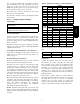
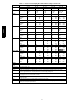
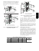
Table 6 – 569J*12-14D/E Piping Recommendations (Two-Circuit Unit)
NOTE: 569J***D/E requires TWO sets of refrigeration piping
R---410A Equivalent Length
Ft 0 --- 3 8 38--- 75 75---113 113---150 150--- 188
m 0 --- 1 2 12--- 23 23--- 34 34--- 46 46--- 57
Model
Linear Length
Ft 0 --- 2 5 25--- 50 50---75 75--- 100 100--- 125
m 0 --- 8 8 --- 1 5 15--- 23 23--- 30 30--- 38
569J*12D/E Liquid Line
3
/
8
3
/
8
3
/
8
1
/
2
3
/
8
1
/
2
3
/
8
1
/
2
Max Lift (ft)
Novation 25 50 28 75 DNU 100 DNU 99
RTPF 25 50 75 NR 83 100 62 125
Suction Line
7
/
8
7
/
8
1
1
/
8
1
1
/
8
1
1
/
8
Charge (lbs ) (ea cir c uit)
Novati on 7.1 8.1 9.6 11.9 DNU 13.8 DNU 15.8
RTPF 13.3 14.3 15.8 NR 16.9 20.0 18.1 22.0
569J*14D/E Liquid Line
3
/
8
3
/
8
3
/
8
1
/
2
3
/
8
1
/
2
3
/
8
1
/
2
Max Lift (ft)
Novation 25 50 48 75 DNU 100 DNU 122
RTPF 25 50 75 NR 54 100 45 125
Suction Line
7
/
8
7
/
8
1
1
/
8
1
1
/
8
1
1
/
8
Charge (lbs ) (ea cir c uit)
Novati on 9.7 10.7 14.5 DNU 16.4 DNU 18.4
RTPF 23.0 24.0 27.8 NR 26.6 29.7 27.8 31.7
Legend:
Equivalent
Length
Equivalent tubing length, including effects of refrigeration specialties devices
Linear Length Linear tubing length, feet
Liquid Line Tubing size, inches OD.
Max Lift Maximum liquid lift (indoor unit ABOVE outdoor unit only), at maximum permitted liquid line pressure drop
S Linear Length Less than 75 ft (23 m): Minimum 2.0° F subcooling entering TXV
S Linear Length Greater than 75 ft (23m): Minimum 0.5° F subcooling entering TXV
Suction Line Tube size, inches OD
See highlighted: Do not use with RTPF coil model
Charge Charge Quantity, lbs. Calculated for both liquid line sizes (where applicable), but only with larger suction line size (where
applicable)
DNU Do Not Use (pressure drop exceeds available subcooling in this model)
NR Not Recommended (use smaller liquid tube size)
NOTE: For applications with equivalent length greater than 188 ft (57 m) and/0r linear length greater than 125 ft (38 m), contact
your local Bryant representative.
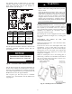
Suction Riser —
A suction riser condition exists when the outdoor unit is
located above the indoor (evaporator) unit and suction vapor
must flow vertically up to return to the compressor. Oil
return is a concern when the suction tube size is too large to
produce the minimum refrigerant velocity to ensure oil
return at minimum load conditions.
Check Table 7 for maximum suction tube size for 569J units
at minimum load conditions. Consider suction speed riser
(reduced tube size for vertical segment only) or double
suction riser arrangement if the proposed suction tube size
does not provide necessary minimum flowrates for this riser.
Vertical Separation (outdoor unit above indoor unit) –
Vertical elevation difference of 200 ft (60 m) is permitted
when the outdoor unit (569J***A/B or 569J***D/E) is
located above the indoor unit.
Insulate Suction Lines —
Apply closed-cell tubular insulation to all suction lines
between evaporator coil connection and 569J unit’s
suction service valve.
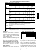
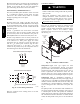
Table 7 –
569J Maximum Suction Pipe Size
Model: Unit Size Maximum Tube Size
569J***A/B 07 1
3
/
8
08 1
5
/
8
12 1
5
/
8
14 2
1
/
8
569J***D/E 12 1
3
/
8
14 1
5
/
8
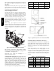
Hot Gas Bypass —
Hot gas bypass, if used, should be introduced before the
evaporator. (A bypass route that also bypasses the evaporator
circuit may lead to oil trapping in the evaporator circuit
during low load conditions and then to oil slugging as
evaporator load increases.) Model 569J units do not include
a hot gas stub connection; a tee must be field-supplied and
installed in the compressor discharge line. Run the hot gas
line between outdoor unit and evaporator coil inlet. Install an
Auxiliary Side Connector at the evaporator between TXV
and distributor (follow instructions for the side connector
part). Insulate the hot gas line.
569J