
Fan User Manual

20
All Units —
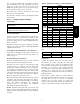
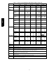
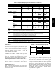
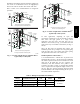
Voltage to compressor terminals during operation must be
within voltage range indicated on unit nameplate. See
Tables 10 and 11. On 3-phase units, voltages between
phases must be balanced within 2% and the current within
10%. Use the formula shown in the legend for Tables 10
and 11, Note 4 (see page 23) to determine the percent of
voltage imbalance. Operation on improper line voltage or
excessive phase imbalance constitutes abuse and may
cause damage to electrical components. Such operation
would invalidate any applicable Bryant warranty.
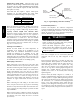
Field Control Wiring —
569J unit control voltage is 24 v. See Fig. 33
(569J***A/B) and Fig. 34 (569J***D/E) for typical field
control connections and the unit’s label diagram for
field-supplied wiring details. Route control wires to the
569J unit through the opening in unit’s end panel to the
connections terminal board in the unit’s control box.
Remainder of the system controls connection will vary
according to the specific construction details of the indoor
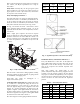
section (air handler or packaged fan coil). Fig. 16
(569J***A/B) and Fig. 17 (569J***D/E) depict typical
connections to a Bryant 524J fan coil unit. Plan for field
connections carefully and install control wiring correctly
per the project plan. Additional components and
supplemental transformer accessory may be required.
The 569J unit requires an external temperature control
device. This device can be a thermostat (field-supplied) or
a thermostat emulation device provided as part of a
third--party Building Management System.
Thermostat —
Install a Bryant-approved accessory thermostat according
to installation instructions included with the accessory.
Locate the thermostat accessory on a solid wall in the
conditioned space to sense average temperature in
accordance with the thermostat installation instructions.
The 569J***A/B unit is a single--stage cooling unit. If no
economizer function is required, select a single--stage
cooling thermostat. If an integrated economizer function is
required, select a two--stage cooling thermostat.
The 569J***D/E is a dual--circuit, two-stage cooling unit.
Select a two—stage cooling thermostat.
Select a thermostat cable or equivalent single leads of
different colors with minimum of four leads for 569J***A/B
or five leads for 569J***D/E unit. Check the thermostat
installation instructions for additional features which might
require additional conductors in the cable.
For wire runs up to 50 ft. (15 m), use no. 18 AWG
(American Wire Gage) insulated wire (35°C minimum).
For50to75ft.(15to23m),useno.16AWGinsulated
wire (35°C minimum). For over 75 ft. (23 m), use no. 14
AWG insulated wire (35°C minimum). All wire sizes
larger than no. 18 AWG cannot be directly connected to
the thermostat and will require a junction box and splice
at the thermostat.
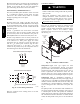
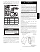
Note 1: Connect only if thermostat requires 24-vac power source.
Note 2: Connect W1 and W2 if supplemental heaters are installed
Field Wiring
(Note 1)
(Note 2)
(Note 2)
C10985
Fig. 16 -- Typical Remote Thermostat Connections
— 569J***A/B
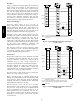
Note 1: Typical multi-function marking. Follow manufacturer’s configuration
instructions to select Y2.
Note 2: Connect only if thermostat requires 24-vac power source.
Note 3: Connect W1 and W2 if supplemental heaters are installed
Field Wiring
(Note 1)
(Note 2)
(Note 3)
(Note 3)
C10078
Fig. 17 -- Typical Remote Thermostat Connections
— 569J***D/E
569J