580J GAS HEAT/ELECTRIC COOLING PACKAGED ROOFTOP 3 TO 12.5 NOMINAL TONS Product Data C08515 (Unit shown with optional louvered hail guard.
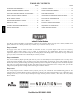
580J TABLE OF CONTENTS PAGE PAGE FEATURES AND BENEFITS . . . . . . . . . . . . . . . . . . . . 3 COOLING TABLES . . . . . . . . . . . . . . . . . . . . . . . . . . . 29 MODEL NUMBER NOMENCLATURE . . . . . . . . . . . . 4 STATIC PRESSURE ADDERS . . . . . . . . . . . . . . . . . . 48 FACTORY OPTIONS AND/OR ACCESSORIES . . . . . 6 FAN PERFORMANCE . . . . . . . . . . . . . . . . . . . . . . . . . 49 AHRI COOLING RATING TABLES . . . . . . . . . . . . . . . 8 OUTDOOR AIR INTAKE & EXHAUST PERF . . . . .
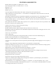
FEATURES AND BENEFITS S Single cooling stage models are available from 3 - 10 ton. S Two cooling stage models are available from 7.5 - 12.5 ton. S SEER up to 13.0. S EER’s up to 11.1. S IEER’s up to 11.8. S Up to 28% lighter than similar industry units. Lighter rooftops make easier replacement jobs. S Utility connections are the same because 3 - 12.5 ton units fit on existing Bryant rooftop curbs. This saves time and money on replacement jobs. S Standardized components and layout.
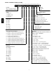
MODEL NUMBER NOMENCLATURE 1 2 3 4 5 8 0 J E 0 5 ____________ 6 7 8 9 6 A 0 ______ 10 11 12 13 14 15 16 17 7 2 A 1 A 0 A A ________ ______ Unit Type Packaging 580J = Cooling/Gas Heat RTU A = Standard Legacy Series w/Puron Refrigerant B = LTL Voltage Factory Installed Options E = 460--- 3--- 60 0A = None J = 208/230--- 1--- 60 P = 208/230--- 3--- 60 Intake/Exhaust Options T = 575--- 3--- 60 A = None 580J B = Temp econo w/ baro relief Cooling Tons E = Temp econo w/ baro rel
Table 1 – FACTORY-- INSTALLED OPTIONS AND FIELD-- INSTALLED ACCESSORIES ITEM Cabinet Thru ---the ---base electrical or gas---line connections Cu/Cu indoor and/or outdoor coils1 Pre ---coated outdoor coils1 Premium, E ---coated outdoor coils1 Perfect Humidity Dehumidification System (3 --- 12.
FACTORY OPTIONS AND/OR ACCESSORIES Economizer (dry--bulb or enthalpy) Power Exhaust with Barometric Relief Economizers save money. They bring in fresh, outside air for ventilation; and provide cool, outside air to cool your building. This is the preferred method of low ambient cooling. When coupled to CO2 sensors, economizers can provide even more savings by coupling the ventilation air to only that amount required. Superior internal building pressure control.
FACTORY OPTIONS AND/OR ACCESSORIES (cont.) The Legacy Line 580J*04-- 14 rooftop coupled with the Perfect Humidity system is capable of operating in normal design cooling mode, subcooling mode, and hot gas reheat mode. Normal design cooling mode is when the unit will operate under its normal sequence of operation by cycling compressors to maintain comfort conditions.
Table 2 – AHRI COOLING RATING TABLE 1-- STAGE COOLING UNIT COOLING STAGES NOM. CAPACITY (TONS) 04A 05A 06A 07A 08A 09A 12A 1 1 1 1 1 1 1 3 4 5 6 7.5 8.5 10 NET COOLING CAPACITY (MBH) 34.6 45.0 59.0 70.0 88.0 97.0 117.0 TOTAL POWER (kW) SEER EER IEER 3.1 4.0 5.5 6.4 8.0 8.8 10.6 13.00 13.00 13.00 N/A N/A N/A N/A 11.00 11.00 10.75 11.00 11.00 11.00 11.00 N/A N/A N/A 11.2 11.2 11.2 11.2 TOTAL POWER (kW) SEER EER IEER 7.5 9.0 10.3 12.9 N/A N/A N/A N/A 11.00 11.00 11.10 10.80 11.7 11.7 11.
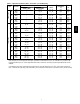
AL/SS HEAT EXCHANGER Units Single Phase 04 05 06 04 05 Three Phase 06 07 08 09 12 14 Gas Heat LOW MED HIGH LOW MED HIGH LOW MED HIGH LOW MED HIGH LOW MED HIGH LOW MED HIGH LOW MED HIGH LOW MED HIGH LOW MED HIGH LOW MED HIGH LOW MED HIGH INPUT / OUTPUT STAGE 1 (MBH) --------------------82 / 66 ------120 / 96 ----120 / 96 ----120 / 96 --120 / 98 180 / 147 --120 / 98 180 / 147 120 / 98 180 / 147 200 / 160 120 / 98 180 / 147 200 / 160 INPUT / OUTPUT STAGE 2 (MBH) 72 / 59 115 / 93 --72 / 59 115 /
Table 5 – HEATING RATING TABLE - LOW NOx1 LOW NOx HEAT EXCHANGER UNIT GAS HEAT LOW MED HIGH LOW MED HIGH LOW MED HIGH LOW MED HIGH LOW MED HIGH LOW MED HIGH Single Phase 04 05 06 Three Phase 580J 04 05 06 INPUT / OUTPUT STAGE 1 (MBH) ------------------------------------- INPUT / OUTPUT STAGE 2 (MBH) 60 / 50 90 / 74 --60 / 50 90 / 74 120 / 101 60 / 50 90 / 74 120 / 101 60 / 50 90 / 74 --60 / 50 90 / 74 120 / 101 60 / 50 90 / 74 120 / 101 TEMP RISE (DEG F) THERMAL EFFICIENCY (%) AFUE (%) 20 --
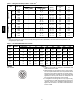
Table 7 – MINIMUM - MAXIMUM AIRFLOW RATINGS - NATURAL GAS & PROPANE 580J*04 580J*05 580J*06 580J*07 580J*08 580J*09 580J*12 580J*14 HEAT LEVEL LOW MED HIGH LOW MED HIGH LOW MED HIGH LOW MED HIGH LOW MED HIGH LOW MED HIGH LOW MED HIGH LOW MED HIGH COOLING HEATING MINIMUM MAXIMUM 900 1500 1200 2000 1500 2500 1800 3000 2250 3750 2550 4250 3000 5000 3600 6000 11 MINIMUM 990 1000 --990 1330 1390 990 1330 1390 990 1330 1390 1900 2100 2270 1900 2100 2270 2100 2620 2650 2100 2620 2650
580J*05A 580J*06A 580J*07A 1 / 1 / Scroll 5--- 10 / --8--- 11 Acutrol 630 / 505 54 / 117 100% 1 / 1 / Scroll 8--- 8 / --14--- 13 Acutrol 630 / 505 54 / 117 100% 1 / 1 / Scroll 10--- 11 / --16--- 0 Acutrol 630 / 505 54 / 117 100% 1 / 1 / Scroll 14--- 2 / --22--- 5 Acutrol 630 / 505 54 / 117 100% Cu / Al 3/8--- in RTPF 2 / 15 5.5 3/4--- in Cu / Al 3/8--- in RTPF 2 / 15 5.5 3/4--- in Cu / Al 3/8--- in RTPF 4 / 15 5.5 3/4--- in Cu / Al 3/8--- in RTPF 4 / 15 7.
Table 9 – PHYSICAL DATA (HEATING) 3 - 6 TONS 580J*04 580J*05 580J*06 580J*07 1 4 --- 13 / 0.18 --- 0.47 11 --- 13 / 0.40 --- 0.47 1 4 --- 13 / 0.18 --- 0.47 11 --- 13 / 0.40 --- 0.47 1 4 --- 13 / 0.18 --- 0.47 11 --- 13 / 0.40 --- 0.47 1 4 --- 13 / 0.18 --- 0.47 11 --- 13 / 0.40 --- 0.47 0.14 0.14 0.14 0.14 0.14 0.14 0.14 0.
580J*09A 580J*09D 1 / 1 / Scroll 13 --- 12 --Acutrol --630 / 505 54 / 117 100% 2 / 2 / Scroll 8 --- 5 / 8 --- 2 13 --- 3 / 13 --- 3 Acutrol 4 --- 6 / 4 --- 6 630 / 505 54 / 117 50% / 100% 1 / 1 / Scroll 15 --- 4 --Acutrol --630 / 505 54 / 117 100% 2 / 2 / Scroll 10 --- 5 / 10 --- 12 16 --- 13 / 16 --- 13 Acutrol --630 / 505 54 / 117 50% / 100% Cu / Al 3/8--- in RTPF 3 / 15 8.9 3/4” Cu / Al 3/8--- in RTPF 3 / 15 8.9 3/4” Cu / Al 3/8--- in RTPF 3 / 15 11.1 3/4” Cu / Al 3/8--- in RTPF 3 / 15 11.
1 / 1 / Scroll 20 --- 0 --Acutrol --630 / 505 54 / 117 100% 2 / 2 / Scroll 10 --- 5 / 10 --- 3 16 --- 10 / 16 --- 0 Acutrol 6 --- 0 / 6 --- 0 630 / 505 54 / 117 50% / 100% 2 / 2 / Scroll 11 --- 0 / 11 --- 6 17 --- 10 / 18 --- 3 Acutrol 7 --- 6 / 8 --- 0 630 / 505 54 / 117 50% / 100% Cu / Al 3/8--- in RTPF 4 / 15 11.1 3/4--- in Cu / Al 3/8--- in RTPF 4 / 15 11.1 3/4--- in Cu / Al 3/8--- in RTPF 4 / 15 11.
Table 12 – PHYSICAL DATA (HEATING) 7.5 - 12.5 TONS 580J*08 580J*09 580J*12 580J*14 1 4 --- 13 / 0.18 --- 0.47 11 --- 13 / 0.40 --- 0.47 1 4 --- 13 / 0.18 --- 0.47 11 --- 13 / 0.40 --- 0.47 1 4 --- 13 / 0.18 --- 0.47 11 --- 13 / 0.40 --- 0.47 1 4 --- 13 / 0.18 --- 0.47 11 --- 13 / 0.40 --- 0.47 0.14 0.14 0.14 0.14 0.14 0.14 0.14 0.
580J CURBS & WEIGHTS DIMENSIONS -- 580J*04--07 C08523 Fig.
580J CURBS & WEIGHTS DIMENSIONS -- 580J*04--07 (cont.) C08599 Fig. 2 -- Dimensions 580J 04--07 C D B A C08337 Fig.
CURBS & WEIGHTS DIMENSIONS -- 580J*04--07 (cont.) CRBTMPWR001A01 CRBTMPWR003A01 B C D ALT DRAIN HOLE 1’-9 11/16” [551] 1’-4” [406] 1 3/4” [44.5] GAS [19] NPT POWER CONTROL ACCESSORY POWER 3/4” 1/2” [12.7] NPT 3/4” [19] NPT 1/2” [12.7] NPT 1/2” [12.7] NPT ROOFCURB ACCESSORY A CRRFCURB001A01 1’-2” [356] CRRFCURB002A01 2’-0” [610] UNIT SIZE 580J* 04-07 NOTES: 1. Roof curb accessory is shipped disassembled. 2. Insulated panels. 3. Dimensions in [ ] are in millimeters. 4.
580J CURBS & WEIGHTS DIMENSIONS -- 580J*08--12 C10496 Fig.
580J CURBS & WEIGHTS DIMENSIONS -- 580J*08--12 (cont.) C08526 Fig. 6 -- 580J 08--12 C D B A C08337 Fig.
CURBS & WEIGHTS DIMENSIONS -- 580J*08--14 ROOFCURB ACCESSORY CRRFCURB003A01 1’ - 2” (356) 2’ - 0” (610) 580J*08 – 14 580J CRRFCURB004A01 UNIT SIZE TYPICAL CORNER FASTENING DEVICE C10481 Fig.
580J CURBS & WEIGHTS DIMENSIONS -- 580J 14 C10508 Fig.
580J CURBS & WEIGHTS DIMENSIONS -- 580J 14 (cont.) C08528 Fig. 10 -- Dimensions 580J--14 C D B A C08337 Fig.
OPTION / ACCESSORY Perfect Humidity1 Power Exhaust --- vertical Power Exhaust --- horizontal EconoMi$er (IV or 2) Two Position damper Manual Dampers Hail Guard (louvered) Cu/Cu Condenser Coil2 Cu/Cu Cond. & Evaporator Coils2 Roof Curb (14---in. curb) Roof Curb (24---in.
APPLICATION DATA Min operating ambient temp (cooling): Outdoor air application strategies: In mechanical cooling mode, your Bryant rooftop unit can safely operate down to an outdoor ambient temperature of 40_F (4_C) and 25_F (-- 4_C), with an accessory winter start kit. It is possible to provide cooling at lower outdoor ambient temperatures by using less outside air, economizers, and/or accessory low ambient kits.
Sizing a rooftop Low ambient applications Bigger isn’t necessarily better. While an air conditioner needs to have enough capacity to meet the design loads, it doesn’t need excess capacity. In fact, excess capacity typically results in very poor part load performance and humidity control. The optional Bryant economizer can adequately cool your space by bringing in fresh, cool outside air. In fact, when so equipped, accessory low ambient kit may not be necessary.
SELECTION PROCEDURE (WITH 580J*07A EXAMPLE)1 I. 580J II. Determine cooling and heating loads. Given: Mixed air dry bulb 80_F (27_C) Mixed air wet bulb 67_F (19_C) Ambient dry bulb 95_F (35_C) 72.0 MBH TCLoad SHCLoad 54.0 MBH Vertical supply air 2100 CFM Heating load 85.0 MBH External static pressure 0.67 in. wg Electrical characteristics 230-- 3-- 60 Make an initial guess at cooling tons. Refrig. tons = TCLoad / 12 MBH per ton Refrig. tons = 72.0 / 12 = 6.
580J*04A (RTPF) 58 EAT (wb) 900 Cfm 62 67 72 76 58 EAT (wb) 1050 Cfm 62 67 72 76 58 EAT (wb) 1200 Cfm 62 67 72 76 58 EAT (wb) 1350 Cfm 62 67 72 76 58 EAT (wb) 1500 Cfm 62 67 72 76 LEGEND: --Cfm EAT(db) EAT(wb) SHC TC ------------- TC SHC TC SHC TC SHC TC SHC TC SHC TC SHC TC SHC TC SHC TC SHC TC SHC TC SHC TC SHC TC SHC TC SHC TC SHC TC SHC TC SHC TC SHC TC SHC TC SHC TC SHC TC SHC TC SHC TC SHC TC SHC 75 28.1 24.4 30.3 22.6 35.5 19.5 39.0 15.3 ----30.2 26.3 31.9 24.6 36.7 20.6 40.1 15.
Table 14 – COOLING CAPACITIES Temp (F) Air Ent Condenser (Edb) 75 85 95 580J 105 115 TC SHC kW TC SHC kW TC SHC kW TC SHC kW TC SHC kW Temp (F) Air Ent Condenser (Edb) 80 75 70 60 50 40 LEGEND Edb --Ewb --kW --Idb --Iwb --SHC --TC --- TC SHC kW TC SHC kW TC SHC kW TC SHC kW TC SHC kW TC SHC kW 1-- STAGE COOLING 580J04 (3 TONS) --- UNIT WITH PERFECT HUMIDITY SYSTEM IN SUBCOOLING MODE Air Entering Evaporator --- CFM 80 dry bulb 80 dry bulb 80 dry bulb 72 wet bulb 67 wet bulb 62 wet bulb 900 12
580J*05A (RTPF) 58 EAT (wb) 1200 Cfm 62 67 72 76 58 EAT (wb) 1400 cfm 62 67 72 76 58 EAT (wb) 1600 Cfm 62 67 72 76 58 EAT (wb) 1800 Cfm 62 67 72 76 58 EAT (wb) 2000 Cfm 62 67 72 76 LEGEND: --Cfm EAT(db) EAT(wb) SHC TC ------------- TC SHC TC SHC TC SHC TC SHC TC SHC TC SHC TC SHC TC SHC TC SHC TC SHC TC SHC TC SHC TC SHC TC SHC TC SHC TC SHC TC SHC TC SHC TC SHC TC SHC TC SHC TC SHC TC SHC TC SHC TC SHC 75 ----43.1 31.2 47.4 25.9 51.1 20.1 ----41.9 36.6 44.6 33.4 48.7 27.3 52.2 20.
Table 16 – COOLING CAPACITIES Temp (F) Air Ent Condenser (Edb) 75 85 95 580J 105 115 TC SHC kW TC SHC kW TC SHC kW TC SHC kW TC SHC kW Temp (F) Air Ent Condenser (Edb) 80 75 70 60 50 40 LEGEND Edb --Ewb --kW --Idb --Iwb --SHC --TC --- TC SHC kW TC SHC kW TC SHC kW TC SHC kW TC SHC kW TC SHC kW 1-- STAGE COOLING 580J05 (4 TONS) --- UNIT WITH PERFECT HUMIDITY SYSTEM IN SUBCOOLING MODE Air Entering Evaporator --- CFM 80 dry bulb 80 dry bulb 80 dry bulb 72 wet bulb 67 wet bulb 62 wet bulb 1200 1
580J*06A (RTPF) 58 EAT (wb) 1500 Cfm 62 67 72 76 58 EAT (wb) 1750 Cfm 62 67 72 76 58 EAT (wb) 2000 Cfm 62 67 72 76 58 EAT (wb) 2250 Cfm 62 67 72 76 58 EAT (wb) 2500 Cfm 62 67 72 76 LEGEND: --Cfm EAT(db) EAT(wb) SHC TC ------------- TC SHC TC SHC TC SHC TC SHC TC SHC TC SHC TC SHC TC SHC TC SHC TC SHC TC SHC TC SHC TC SHC TC SHC TC SHC TC SHC TC SHC TC SHC TC SHC TC SHC TC SHC TC SHC TC SHC TC SHC TC SHC 75 52.9 45.8 56.2 41.8 62.4 34.8 68.2 27.2 ----56.5 48.9 58.5 45.2 64.3 36.9 69.5 27.
Table 18 – COOLING CAPACITIES Temp (F) Air Ent Condenser (Edb) 75 85 95 580J 105 115 TC SHC kW TC SHC kW TC SHC kW TC SHC kW TC SHC kW Temp (F) Air Ent Condenser (Edb) 80 75 70 60 50 40 LEGEND Edb --Ewb --kW --Idb --Iwb --SHC --TC --- TC SHC kW TC SHC kW TC SHC kW TC SHC kW TC SHC kW TC SHC kW 1-- STAGE COOLING 580J06 (5 TONS) --- UNIT WITH PERFECT HUMIDITY SYSTEM IN SUBCOOLING MODE Air Entering Evaporator --- CFM 80 dry bulb 80 dry bulb 80 dry bulb 72 wet bulb 67 wet bulb 62 wet bulb 1750 2
580J*07A (RTPF) 58 EAT (wb) 1800 Cfm 62 67 72 76 58 EAT (wb) 2100 Cfm 62 67 72 76 58 EAT (wb) 2400 Cfm 62 67 72 76 58 EAT (wb) 2700 Cfm 62 67 72 76 58 EAT (wb) 3000 Cfm 62 67 72 76 LEGEND: --Cfm EAT(db) EAT(wb) SHC TC ------------- TC SHC TC SHC TC SHC TC SHC TC SHC TC SHC TC SHC TC SHC TC SHC TC SHC TC SHC TC SHC TC SHC TC SHC TC SHC TC SHC TC SHC TC SHC TC SHC TC SHC TC SHC TC SHC TC SHC TC SHC TC SHC 75 64.9 56.6 68.7 51.7 75.6 42.8 82.6 33.5 ----68.9 60.1 70.9 55.6 77.8 45.4 84.5 34.
Table 20 – COOLING CAPACITIES Temp (F) Air Ent Condenser (Edb) 75 85 95 580J 105 115 TC SHC kW TC SHC kW TC SHC kW TC SHC kW TC SHC kW Temp (F) Air Ent Condenser (Edb) 80 75 70 60 50 40 LEGEND Edb --Ewb --kW --Idb --Iwb --SHC --TC --- TC SHC kW TC SHC kW TC SHC kW TC SHC kW TC SHC kW TC SHC kW 1-- STAGE COOLING 580J07 (6 TONS) --- UNIT WITH PERFECT HUMIDITY SYSTEM IN SUBCOOLING MODE Air Entering Evaporator --- CFM 80 dry bulb 80 dry bulb 80 dry bulb 72 wet bulb 67 wet bulb 62 wet bulb 2100 2
580J*08A (RTPF) 58 EAT (wb) 2250 Cfm 62 67 72 76 58 EAT (wb) 2625 Cfm 62 67 72 76 58 EAT (wb) 3000 Cfm 62 67 72 76 58 EAT (wb) 3375 Cfm 62 67 72 76 62 EAT (wb) 3750 Cfm 58 67 72 76 LEGEND: --Cfm EAT(db) EAT(wb) SHC TC ------------- TC SHC TC SHC TC SHC TC SHC TC SHC TC SHC TC SHC TC SHC TC SHC TC SHC TC SHC TC SHC TC SHC TC SHC TC SHC TC SHC TC SHC TC SHC TC SHC TC SHC TC SHC TC SHC TC SHC TC SHC TC SHC 75 81.2 70.5 86.9 63.6 95.2 52.8 103.5 41.5 ----85.9 74.6 89.6 68.1 97.9 55.7 106.
Table 22 – COOLING CAPACITIES 580J*08D (RTPF & Novation) 58 EAT (wb) 2250 Cfm 62 67 72 76 EAT (wb) 2625 Cfm 62 67 72 76 58 EAT (wb) 3000 Cfm 62 67 72 76 58 EAT (wb) 3375 Cfm 62 67 72 76 58 62 EAT (wb) 3750 Cfm 580J 58 67 72 76 LEGEND: --Cfm EAT(db) EAT(wb) SHC TC ------------- TC SHC TC SHC TC SHC TC SHC TC SHC TC SHC TC SHC TC SHC TC SHC TC SHC TC SHC TC SHC TC SHC TC SHC TC SHC TC SHC TC SHC TC SHC TC SHC TC SHC TC SHC TC SHC TC SHC TC SHC TC SHC 75 77.4 66.9 82.2 60.8 90.1 50.2 98.
2-- STAGE COOLING (RTPF ONLY) 580J08 COOLING CAPACITIES, UNIT WITH PERFECT HUMIDITY SYSTEM IN SUBCOOLING MODE AIR ENTERING EVAPORATOR --- CFM 2250/0.05 3000/0.07 3750/0.09 TEMP (F) AIR ENT CONDENSER (Edb) Air Entering Evaporator --- Ewb (F) 72 67 62 72 67 62 72 67 TC 103.05 93.02 83.60 109.77 99.52 90.08 114.01 103.69 75 SHC 43.66 55.34 67.09 50.99 66.29 81.31 57.49 76.27 kW 4.90 4.83 4.77 4.82 4.88 4.96 4.99 4.91 TC 95.39 85.83 76.88 101.59 91.89 82.95 105.53 95.76 85 SHC 36.42 48.47 60.60 43.24 58.99 74.
Table 24 – COOLING CAPACITIES 580J*09A (RTPF) 58 EAT (wb) 2550 Cfm 62 67 72 76 EAT (wb) 2975 Cfm 62 67 72 76 58 EAT (wb) 3400 Cfm 62 67 72 76 58 EAT (wb) 3825 Cfm 62 67 72 76 58 EAT (wb) 62 4250 Cfm 580J 58 67 72 76 LEGEND: --Cfm EAT(db) EAT(wb) SHC TC ------------- TC SHC TC SHC TC SHC TC SHC TC SHC TC SHC TC SHC TC SHC TC SHC TC SHC TC SHC TC SHC TC SHC TC SHC TC SHC TC SHC TC SHC TC SHC TC SHC TC SHC TC SHC TC SHC TC SHC TC SHC TC SHC 75 88.1 76.4 93.9 69.4 103.8 57.8 113.1 45.
580J*09D (RTPF) 58 EAT (wb) 2550 Cfm 62 67 72 76 58 EAT (wb) 2975 Cfm 62 67 72 76 58 EAT (wb) 3400 Cfm 62 67 72 76 58 EAT (wb) 3825 Cfm 62 67 72 76 58 EAT (wb) 4250 Cfm 62 67 72 76 LEGEND: --Cfm EAT(db) EAT(wb) SHC TC ------------- TC SHC TC SHC TC SHC TC SHC TC SHC TC SHC TC SHC TC SHC TC SHC TC SHC TC SHC TC SHC TC SHC TC SHC TC SHC TC SHC TC SHC TC SHC TC SHC TC SHC TC SHC TC SHC TC SHC TC SHC TC SHC 75 89.7 77.8 94.3 71.0 105.0 59.0 115.9 46.4 ----95.3 82.6 97.9 76.7 108.5 62.8 119.
580J Table 26 – COOLING CAPACITIES 2-- STAGE COOLING (RTPF ONLY) 580J09 COOLING CAPACITIES, UNIT WITH PERFECT HUMIDITY SYSTEM IN SUBCOOLING MODE AIR ENTERING EVAPORATOR --- CFM 2550/0.04 3400/0.05 4250/0.07 TEMP (F) AIR ENT CONDENSER (Edb) Air Entering Evaporator --- Ewb (F) 72 67 62 72 67 62 72 67 TC 119.20 107.44 96.41 126.95 114.98 103.92 131.87 119.81 75 SHC 50.63 63.94 77.40 59.17 76.72 94.21 66.80 88.44 kW 5.67 5.57 5.47 5.54 5.63 5.74 5.79 5.68 TC 110.40 99.22 88.76 117.63 106.26 95.77 122.21 110.
580J*12A (RTPF) 58 EAT (wb) 3000 Cfm 62 67 72 76 58 EAT (wb) 3500 Cfm 62 67 72 76 58 EAT (wb) 4000 Cfm 62 67 72 76 58 EAT (wb) 4500 Cfm 62 67 72 76 62 EAT (wb) 5000 Cfm 58 67 72 76 LEGEND: --Cfm EAT(db) EAT(wb) SHC TC ------------- TC SHC TC SHC TC SHC TC SHC TC SHC TC SHC TC SHC TC SHC TC SHC TC SHC TC SHC TC SHC TC SHC TC SHC TC SHC TC SHC TC SHC TC SHC TC SHC TC SHC TC SHC TC SHC TC SHC TC SHC TC SHC 75 106.3 92.2 112.5 83.8 123.5 69.2 134.3 53.8 ----112.9 97.9 116.3 90.2 126.9 73.
Table 28 – COOLING CAPACITIES 580J*12D (RTPF & Novation) 58 EAT (wb) 3000 Cfm 62 67 72 76 EAT (wb) 3500 Cfm 62 67 72 76 58 EAT (wb) 4000 Cfm 62 67 72 76 58 EAT (wb) 4500 Cfm 62 67 72 76 58 62 EAT (wb) 5000 Cfm 580J 58 67 72 76 LEGEND: --Cfm EAT(db) EAT(wb) SHC TC ------------- TC SHC TC SHC TC SHC TC SHC TC SHC TC SHC TC SHC TC SHC TC SHC TC SHC TC SHC TC SHC TC SHC TC SHC TC SHC TC SHC TC SHC TC SHC TC SHC TC SHC TC SHC TC SHC TC SHC TC SHC TC SHC 75 107.6 93.2 113.6 84.6 124.4 69.
2-- STAGE COOLING (RTPF ONLY) 10 TONS 580J12 COOLING CAPACITIES, UNIT WITH PERFECT HUMIDITY SYSTEM IN SUBCOOLING MODE AIR ENTERING EVAPORATOR --- CFM 3000/0.04 4000/0.06 5000/0.07 TEMP (F) AIR ENT CONDENSER (Edb) Air Entering Evaporator --- Ewb (F) 72 67 62 72 67 62 72 67 TC 142.85 129.44 116.93 152.09 138.44 125.76 157.99 144.23 75 SHC 58.38 74.88 91.58 67.96 89.45 111.02 76.63 102.94 kW 7.19 6.97 6.79 6.92 7.12 7.35 7.45 7.22 TC 132.33 119.68 107.86 140.92 128.03 116.10 146.41 133.41 85 SHC 48.44 65.
Table 30 – COOLING CAPACITIES 580J*14D (RTPF & Novation) 58 EAT (wb) 3600 Cfm 62 67 72 76 EAT (wb) 4200 Cfm 62 67 72 76 58 EAT (wb) 4800 Cfm 62 67 72 76 58 EAT (wb) 5400 Cfm 62 67 72 76 58 62 EAT (wb) 6000 Cfm 580J 58 67 72 76 LEGEND: --Cfm EAT(db) EAT(wb) SHC TC ------------- TC SHC TC SHC TC SHC TC SHC TC SHC TC SHC TC SHC TC SHC TC SHC TC SHC TC SHC TC SHC TC SHC TC SHC TC SHC TC SHC TC SHC TC SHC TC SHC TC SHC TC SHC TC SHC TC SHC TC SHC TC SHC 75 127.6 110.3 136.1 96.6 146.2 78.
2-- STAGE COOLING (RTPF ONLY) 12.5 TONS 580J14 COOLING CAPACITIES, UNIT WITH PERFECT HUMIDITY SYSTEM IN SUBCOOLING MODE AIR ENTERING EVAPORATOR --- CFM 3750/0.02 5000/0.06 6250/0.05 TEMP (F) AIR ENT CONDENSER (Edb) Air Entering Evaporator --- Ewb (F) 72 67 62 72 67 62 72 67 TC 183.66 166.86 151.43 194.90 177.83 162.05 201.97 184.84 75 SHC 79.39 100.52 121.91 91.70 119.42 147.05 102.94 137.00 kW 9.82 9.63 9.46 9.58 9.76 9.96 10.04 9.84 TC 172.71 156.78 142.09 183.32 167.13 152.17 189.98 173.73 85 SHC 69.
Table 32 – STATIC PRESSURE ADDERS (Factory Options and/or Accessories) Economizer 3 --- 6 TONS CFM (in. wg) Vertical Economizer Horizontal Economizer 600 800 1000 1250 1500 1750 2000 2250 2500 2750 3000 0.01 0.02 0.04 0.05 0.07 0.09 0.12 0.15 0.18 0.22 0.26 0.02 0.03 0.04 0.06 0.08 0.10 0.13 0.15 0.18 0.23 0.28 7.5 --- 12.5 TONS 580J CFM (in. wg) Vertical Economizer Horizontal Economizer 2250 2500 2750 3000 3250 3500 3750 4000 4250 4500 4750 5000 5250 5500 5750 6000 0.06 0.
FAN PERFORMANCE CFM 900 975 1050 1125 1200 1275 1350 1425 1500 CFM 900 975 1050 1125 1200 1275 1350 1425 1500 1 PHASE 0.2 RPM BHP Field Supplied Drive1 553 0.14 575 0.16 597 0.18 620 0.21 643 0.23 667 0.27 691 0.30 715 0.34 740 0.38 1.2 RPM BHP 1019 1036 1053 1071 1089 1107 1126 1144 1163 0.64 0.69 0.74 0.79 0.84 0.90 0.96 1.03 1.10 RPM 681 700 720 741 762 783 805 827 849 3 TON HORIZONTAL SUPPLY AVAILABLE EXTERNAL STATIC PRESSURE (in. wg) 0.4 0.6 0.8 1.
FAN PERFORMANCE (cont.) Table 35 – 580J*04 CFM 580J 900 975 1050 1125 1200 1275 1350 1425 1500 CFM 900 975 1050 1125 1200 1275 1350 1425 1500 3 PHASE 0.2 RPM BHP Field Supplied Drive1 553 0.14 575 0.16 597 0.18 620 0.21 643 0.23 667 0.27 691 0.30 715 0.34 740 0.38 1.2 RPM BHP 1019 1036 1053 1071 1089 1107 1126 1144 1163 0.64 0.69 0.74 0.79 0.84 0.90 0.96 1.03 1.10 3 TON HORIZONTAL SUPPLY AVAILABLE EXTERNAL STATIC PRESSURE (in. wg) 0.4 0.6 0.8 1.
FAN PERFORMANCE (cont.) CFM 1200 1300 1400 1500 1600 1700 1800 1900 2000 CFM 1200 1300 1400 1500 1600 1700 1800 1900 2000 1 PHASE 4 TON HORIZONTAL SUPPLY AVAILABLE EXTERNAL STATIC PRESSURE (in. wg) 0.4 0.6 0.8 BHP RPM BHP RPM BHP RPM BHP Standard Static Option Medium Static Option 0.23 762 0.34 859 0.46 944 0.58 0.28 790 0.40 886 0.52 969 0.65 0.33 819 0.45 913 0.58 996 0.72 0.38 849 0.52 941 0.66 1023 0.80 0.45 879 0.59 970 0.73 1050 0.88 0.52 910 0.67 999 0.82 1078 0.98 0.59 942 0.75 1029 0.
FAN PERFORMANCE (cont.) Table 39 – 580J*05 CFM 580J 1200 1300 1400 1500 1600 1700 1800 1900 2000 CFM 1200 1300 1400 1500 1600 1700 1800 1900 2000 3 PHASE 4 TON HORIZONTAL SUPPLY AVAILABLE EXTERNAL STATIC PRESSURE (in. wg) 0.4 0.6 0.8 BHP RPM BHP RPM BHP RPM BHP Standard Static Option Medium Static Option 0.23 762 0.34 859 0.46 944 0.58 0.28 790 0.40 886 0.52 969 0.65 0.33 819 0.45 913 0.58 996 0.72 0.38 849 0.52 941 0.66 1023 0.80 0.45 879 0.59 970 0.73 1050 0.88 0.52 910 0.67 999 0.82 1078 0.98 0.
FAN PERFORMANCE (cont.) CFM 1500 1625 1750 1875 2000 2125 2250 2375 2500 CFM 1500 1625 1750 1875 2000 2125 2250 2375 2500 1 PHASE 0.2 RPM BHP RPM 800 849 899 950 1001 1053 1106 1159 --- 0.39 0.48 0.59 0.70 0.84 0.99 1.16 1.34 --- 904 947 992 1038 1085 1133 1182 1231 --- 1.2 RPM BHP RPM 1247 1276 1308 1342 ----------- 0.98 1.10 1.22 1.37 ----------- 1320 1348 1377 ------------- 5 TON HORIZONTAL SUPPLY AVAILABLE EXTERNAL STATIC PRESSURE (in. wg) 0.4 0.6 0.
FAN PERFORMANCE (cont.) Table 43 – 580J*06 CFM 580J 1500 1625 1750 1875 2000 2125 2250 2375 2500 CFM 1500 1625 1750 1875 2000 2125 2250 2375 2500 3 PHASE 0.2 RPM BHP RPM 800 849 899 950 1001 1053 1106 1159 1212 0.39 0.48 0.59 0.70 0.84 0.99 1.16 1.34 1.55 904 947 992 1038 1085 1133 1182 1231 1281 1.2 RPM BHP RPM 1247 1276 1308 1342 1377 1414 1452 1492 1533 0.98 1.10 1.22 1.37 1.53 1.71 1.91 2.12 2.
FAN PERFORMANCE (cont.) CFM 1800 1950 2100 2250 2400 2550 2700 2850 3000 CFM 1800 1950 2100 2250 2400 2550 2700 2850 3000 3 PHASE 0.2 RPM BHP Field Supplied Drive1 913 0.64 972 0.78 1032 0.95 1093 1.14 1155 1.36 1217 1.60 1280 1.87 1343 2.17 1406 2.50 RPM 1010 1065 1120 1177 1234 1293 1352 1412 1472 6 TON HORIZONTAL SUPPLY AVAILABLE EXTERNAL STATIC PRESSURE (in. wg) 0.4 0.6 0.8 BHP RPM BHP RPM Standard Static Option 0.80 1098 0.98 1178 0.96 1148 1.14 1226 1.14 1200 1.33 1275 1.34 1254 1.55 1325 1.
FAN PERFORMANCE (cont.) Table 47 – 580J*08 CFM 580J 2250 2438 2625 2813 3000 3188 3375 3563 3750 CFM 2250 2438 2625 2813 3000 3188 3375 3563 3750 3 PHASE 0.2 RPM BHP RPM 505 533 562 591 621 652 682 713 745 0.52 0.62 0.74 0.88 1.03 1.21 1.40 1.61 1.85 586 610 635 661 688 715 743 772 801 1.2 RPM BHP 838 854 872 890 910 930 951 973 996 1.81 1.96 2.12 2.31 2.51 2.74 2.99 3.26 3.55 7.5 TON HORIZONTAL SUPPLY AVAILABLE EXTERNAL STATIC PRESSURE (in. wg) 0.4 0.6 0.
FAN PERFORMANCE (cont.) CFM 2550 2763 2975 3188 3400 3613 3825 4038 4250 CFM 2550 2763 2975 3188 3400 3613 3825 4038 4250 3 PHASE 0.2 RPM BHP Field---Supplied Drive1 497 0.48 524 0.58 551 0.70 580 0.84 609 1.00 638 1.17 668 1.37 698 1.59 728 1.83 1.2 RPM BHP 833 849 865 883 902 921 941 963 984 1.21 1.36 1.52 1.70 1.90 2.13 2.37 2.63 2.92 RPM 579 602 626 651 677 703 730 758 786 8.5 TON HORIZONTAL SUPPLY AVAILABLE EXTERNAL STATIC PRESSURE (in. wg) 0.4 0.6 0.
FAN PERFORMANCE (cont.) Table 51 – 580J*12 CFM 580J 3000 3250 3500 3750 4000 4250 4500 4750 5000 CFM 3000 3250 3500 3750 4000 4250 4500 4750 5000 3 PHASE 0.2 RPM BHP Field Supplied Drive1 579 0.70 613 0.85 648 1.03 683 1.23 719 1.45 756 1.71 792 1.99 830 2.31 867 2.66 RPM 660 690 721 753 786 819 853 888 923 1.2 RPM BHP RPM 917 938 961 985 1011 1037 1064 1091 1120 1.70 1.93 2.18 2.46 2.76 3.09 3.46 3.85 4.
FAN PERFORMANCE (cont.) CFM 3438 3750 4063 4375 4688 5000 5313 5625 5938 6250 CFM 3438 3750 4063 4375 4688 5000 5313 5625 5938 6250 3 PHASE 0.2 RPM BHP RPM 639 683 728 774 820 867 914 962 1009 --- 0.98 1.23 1.52 1.85 2.23 2.66 3.15 3.69 4.30 --- 713 753 794 836 879 923 967 1012 1058 --- 1.2 RPM BHP 955 985 1017 1050 1084 1120 --------- 2.12 2.46 2.84 3.27 3.75 4.28 --------- 12.5 TON HORIZONTAL SUPPLY AVAILABLE EXTERNAL STATIC PRESSURE (in. wg) 0.4 0.6 0.
FAN PERFORMANCE (cont.) Table 55 – PULLEY ADJUSTMENT 1 phase 1 phase 3 phase 05 3 phase 3 phase 3 phase 3 phase 3 phase 3 phase 06 07 08 09 12 14 580J 3 phase 04 1 phase UNIT MOTOR/DRIVE COMBO 0.0 0.5 1.0 MOTOR PULLEY TURNS OPEN 1.5 2.0 2.5 3.0 3.5 4.0 4.5 5.
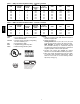
ECONOMIZER, BAROMETRIC RELIEF AND PE PERFORMANCE 2500 Horizontal Economizers 2000 1500 RELIEF FLOW (CFM) RELIEF FLOW (CFM) 2500 3 -6 Ton 7½ - 12½ Ton 1000 500 Vertical Economizers 2000 1500 3 -6 Ton 7½ - 12½ Ton 1000 500 0 0 0 0.05 0.1 0.15 0.2 0.25 0 0.3 0.05 0.1 0.15 0.2 0.25 0.3 RETURN DUCT STATIC PRESSURE (in. wg) RETURN DUCT STATIC PRESSURE (in. wg) C08070 C08073 6000 Horizontal Economizers 5000 4000 3 - 6 TON 7 1/2 - 12 1/2 Ton 3000 580J 6000 Fig.
ELECTRICAL INFORMATION 580J Table 56 – 580J*04A 1-- Stage Cooling V ---Ph---Hz VOLTAGE RANGE MIN MAX RLA LRA WATTS FLA 208--- 1--- 60 187 253 16.6 79 325 1.5 230--- 1--- 60 187 253 16.6 79 325 1.5 208--- 3--- 60 187 253 10.4 73 325 1.5 230--- 3--- 60 187 253 10.4 73 325 1.5 460--- 3--- 60 414 506 5.8 38 325 0.8 575--- 3--- 60 518 633 3.8 37 325 0.
ELECTRICAL INFORMATION (cont.) V ---Ph---Hz 1-- Stage Cooling VOLTAGE RANGE COMP (ea) OFM (ea) IFM RLA LRA WATTS FLA 253 19.0 123 325 1.5 187 253 19.0 123 325 1.5 460--- 3--- 60 414 506 9.7 62 325 0.8 575--- 3--- 60 518 633 7.4 50 325 0.
ELECTRICAL INFORMATION (cont.) Table 62 – 580J*09A 580J V ---Ph---Hz 1-- Stage Cooling VOLTAGE RANGE COMP (ea) OFM (ea) IFM RLA LRA WATTS FLA 253 29.5 195 325 1.5 187 253 29.5 195 325 1.5 460--- 3--- 60 414 506 14.7 95 325 0.8 575--- 3--- 60 518 633 12.2 80 325 0.6 MIN MAX 208--- 3--- 60 187 230--- 3--- 60 Table 63 – 580J*09D V ---Ph---Hz 8.
ELECTRICAL INFORMATION (cont.) V ---Ph---Hz 2-- Stage Cooling VOLTAGE RANGE COMP (Cir 1) COMP (Cir 2) 10 TONS OFM (ea) RLA LRA RLA LRA WATTS FLA MIN MAX 208--- 3--- 60 187 253 15.6 110 15.9 110 325 1.5 230--- 3--- 60 187 253 15.6 110 15.9 110 325 1.5 460--- 3--- 60 414 506 7.7 52 7.7 52 325 0.8 575--- 3--- 60 518 633 5.8 39 5.7 39 325 0.
UNIT Table 67 – MCA/MOCP DETERMINATION NO C.O. OR UNPWRD C.O. NOM.
208/230--- 3--- 60 460--- 3--- 60 575--- 3--- 60 208/230--- 3--- 60 460--- 3--- 60 575--- 3--- 60 208/230--- 3--- 60 460--- 3--- 60 575--- 3--- 60 208/230--- 3--- 60 460--- 3--- 60 580J*12(D,F,K,M) 575--- 3--- 60 208/230--- 3--- 60 208/230--- 3--- 60 460--- 3--- 60 575--- 3--- 60 460--- 3--- 60 575--- 3--- 60 IFM TYPE STD MED HIGH STD MED HIGH STD MED HIGH STD MED HIGH STD MED HIGH STD MED HIGH STD MED HIGH STD MED HIGH STD MED HIGH STD MED HIGH STD MED HIGH STD MED HIGH STD MED HIGH STD MED HIGH STD
580J TABLE 67 (cont.) MCA/MOCP DETERMINATION NO C.O. OR UNPWRD C.O. LEGEND: C.O. --- Convenience outlet DISC --- Disconnect FLA --- Full load amps IFM --- Indoor fan motor LRA --- Locked rotor amps MCA --- Minimum circuit amps MOCP --- Maximum over current protection P.E. --- Power exhaust UNPWRD CO --- Un --- powered convenient outlet NOTES: 1.
NOM.
UNIT 580J*08(D,F,K,M) 208/230--- 3--- 60 460--- 3--- 60 575--- 3--- 60 208/230--- 3--- 60 460--- 3--- 60 575--- 3--- 60 208/230--- 3--- 60 460--- 3--- 60 575--- 3--- 60 208/230--- 3--- 60 460--- 3--- 60 575--- 3--- 60 580J*12(D,F,K,M) 580J*12(A,C) 580J*09(D,F,K,M) 580J*09(A,C) NOM. V ---Ph---Hz 208/230--- 3--- 60 580J*14(D,F,K,M) 580J TABLE 68 (cont.) MCA/MOCP DETERMINATION W/ PWRD C.O.
580J TYPICAL WIRING DIAGRAMS C08518 Fig.
580J TYPICAL WIRING DIAGRAMS (cont.) C08577 Fig.
Fig.
Fig.
SEQUENCE OF OPERATION The sequence below describes the sequence of operation for an electromechanical unit with and without a factory installed EconoMi$er IV (called “economizer” in this sequence). For information regarding a direct digital controller, see the start-- up, operations, and troubleshooting manual for the applicable controller. Electromechanical units with no economizer Cooling — When the thermostat calls for cooling, terminals G and Y1 are energized.
580J SEQUENCE OF OPERATION (cont.) On the initial power to the EconoMi$er IV control, it will take the damper up to 2 1/2 minutes before it begins to position itself. After the initial power-- up, further changes in damper position can take up to 30 seconds to initiate. Damper movement from full closed to full open (or vice versa) will take between 1 1/2 and 2 1/2 minutes.
SEQUENCE OF OPERATION (cont.) RH2.x RH1.x COND COIL COMP PERFECT HUMIDITY COIL CV.x OUTDOOR AIR METERING DEVICE 580J EVAP COIL CLOSED VALVE OPEN VALVE INDOOR ENTERING AIR a48-8173 C09456 Subcooling Mode (Reheat 1) -- Perfect Humidity System (580J04--14) RH2.x RH1.x COND COIL COMP PERFECT HUMIDITY COIL CV.
GUIDE SPECIFICATIONS -- 580J*04--14 Note about this specification: Bryant wrote this specification in the 2004 version of the “Masterformat” as published by the Construction Specification Institute. Please feel free to copy this specification directly into your building spec. Gas Heat/Electric Cooling Packaged Rooftop HVAC Guide Specifications 580J Size Range: 3 to 12.5 Nominal Tons Section Description 23 06 80 Schedules for Decentralized HVAC Equipment 23 06 80.
11. Shall have a battery back-- up capable of a minimum of 10,000 hours of data and time clock retention during power outages. 12. Shall have built-- in support for Bryant technician tool. 13. Shall include an EIA-- 485 protocol communication port, an access port for connection of either a computer or a Bryant technician tool, an EIA-- 485 port for network communication to intelligent space sensors and displays, and a port to connect an optional LonWorks communications card. 14.
580J 2. Factory assembled, single-- piece heating and cooling rooftop unit. Contained within the unit enclosure shall be all factory wiring, piping, controls, and special features required prior to field start-- up. 3. Unit shall use environmentally sound, Puron refrigerant. 4. Unit shall be installed in accordance with the manufacturer’s instructions. 5. Unit must be selected and installed in compliance with local, state, and federal codes. 23 81 19.13.B. Quality Assurance 1. Unit meets ASHRAE 90.
580J 5. Base Rail a. Unit shall have base rails on a minimum of 2 sides. b. Holes shall be provided in the base rails for rigging shackles to facilitate maneuvering and overhead rigging. c. Holes shall be provided in the base rail for moving the rooftop by fork truck. d. Base rail shall be a minimum of 16 gauge thickness. 6. Condensate pan and connections: a. Shall be a sloped condensate drain pan made of a non-- corrosive material. b. Shall comply with ASHRAE Standard 62. c.
580J c. Burners shall incorporate orifices for rated heat output up to 2000 ft (610m) elevation. Additional accessory kits may be required for applications above 2000 ft (610m) elevation, depending on local gas supply conditions. d. Each heat exchanger tube shall contain multiple dimples for increased heating effectiveness. 4. Optional Stainless Steel Heat Exchanger construction a. Use energy saving, direct-- spark ignition system. b. Use a redundant main gas valve. c.
580J 5. Standard All Aluminum Novation Coils: a. Standard condenser coils shall have all aluminum NOVATION Heat Exchanger Technology design consisting of aluminum multi port flat tube design and aluminum fin. Coils shall be a furnace brazed design and contain epoxy lined shrink wrap on all aluminum to copper connections. b. Condenser coils shall be leak tested to 150 psig, pressure tested to 650 psig, and qualified to UL 1995 burst test at 1980 psig. 6.
580J b. Shall use sealed, permanently lubricated ball-- bearing type. c. Blower fan shall be double-- inlet type with forward-- curved blades. d. Shall be constructed from steel with a corrosion resistant finish and dynamically balanced. 23 81 19.13.N. Condenser Fans and Motors 1. Condenser fan motors: a. Shall be a totally enclosed motor. b. Shall use permanently lubricated bearings. c. Shall have inherent thermal overload protection with an automatic reset feature. d.
580J 4. Perfect Humidity Dehumidification System: a. The Perfect Humidity Dehumidification System shall be factory installed in single stage 580J04-- 07 and two stage 580J08-- 14 models with RTPF (round tube plate tin) condenser coils, and shall provide greater dehumidification of the occupied space by two modes of dehumidification operations in addition to its normal design cooling mode: (1.
580J b. Minimum of four connection locations per unit. 13. Propeller Power Exhaust: a. Power exhaust shall be used in conjunction with an integrated economizer. b. Independent modules for vertical or horizontal return configurations shall be available. c. Horizontal power exhaust is shall be mounted in return ductwork. d. Power exhaust shall be controlled by economizer controller operation. Exhaust fans shall be energized when dampers open past the 0-- 100% adjustable setpoint on the economizer control.