
Operating instructions

staging timers. (See timers explanation below.) The AC Control
supports only single stage heat and cool. The HP control supports
two stage cooling, two stage furnace heating, and three stage HP
heating (lo HP, hi HP, hi HP + aux heat.)
Emergency Heat
Emergency heat (aux heat without compressor heat) can be
selected for a HP system by either of two ways: First, by selecting
Eheat using the Eheat override switch on the HP Control, or
second, selection of Eheat on each of the thermostats, provided
they have the Eheat function. When either of these Eheat selections
is made, a heating demand provides a W signal without a Y signal
to the equipment.
NOTE: The second Eheat method requires HP thermostats and
that they all must be set to Eheat.
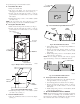
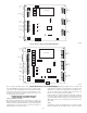
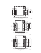
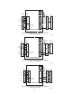
Indicator LEDs
There are 7 indicator LEDs on the AC Control and an additional 3
on the HP/2S Control. Their locations are shown on Fig. 8 and 9.
Each damper has its own green LED which is ON when the
damper opens due to a calling condition or partially open due to an
LAT or HPT limit condition.
Each equipment output has its own LED which is on when that
output is energized. Y and O outputs are yellow, W outputs are red
and the G output is green.
In addition, there is a status LED whose operation is described
under the section Error Codes.
Timers
To control excessive equipment cycling or rapid staging up, the
control has two timers. The cycle timer prevents the same stage
from turning on within 10 minutes of the last time it turned on.
This allows a stage to turn on for as short or as long as the
thermostats request, but will not allow more than six cycles per
hour.
The staging timer prevents a higher stage from turning on until the
next stage below it has been on for 15 minutes. This minimizes use
of electric heat with heat HP systems.
There is also a timegaurd timer which will not allow the compres-
sor to be turned on until it has been off for five minutes.
A changeover timer, which can be set from 0 to 30 minutes, limits
the control’s ability to switch between heating and cooling. The
opposite mode is prevented from coming on until the first mode
has been satisfied for the selected time.
Timer Override
A momentary switch is located near the bottom of the control
circuit board. Pressing it momentarily overrides all of the system
timers, allowing the control to immediately jump to the highest
calling stage.
Temperature Limits and Sensors
Both the AC and HP controls have a LAT (leaving air temperature)
sensor which is to be placed in the downstream air path of the
heating /cooling equipment. It is used in both heating and cooling
to limit LAT to a safe value. It must be connected. The system will
not operate without it. Its setting is fixed for cooling and is
adjustable in four settings for heating. Selection of best setting is
discussed under LAT Limit Selection.
The HP control also has an optional HPT Sensor (heat pump
temperature) which is to be placed downstream of the coil but
ahead of the electric heater. This sensor measures the temperature
of the air leaving the coil during HP heating. It is not included with
the control, but may be ordered separately as part number
TSATXXSEN01-B. A 10K ohm resistor is factory installed in its
place when the actual sensor is not used. In the HP control only,
dipswitch 11 allows the installer to temporarily disable both the
LAT and the HPT sensors. Disabling of these sensors is only to be
done on a temporary basis.
CAUTION: UNIT DAMAGE HAZARD
Failure to follow this caution could result in unit damage.
Operating equipment with sensors disabled can cause
permanent damage to HVAC equipment.
Bypass
The purpose of a bypass is to limit noise in the duct system when
the dampers are excessively restricting it. When a direct bypass
(outlet air fed back directly into the return) is used, bypassing
decreases entering air temperature in cooling and increases it in
heating. Excessive bypassing will lead to limit trips, either through
the LAT /HPT sensors or the equipment internal limits.
Setting the Bypass
Setting the bypass is a balance between too much noise (bypass
trip pressure set too high) and excessive bypassing which will
cause limit trips, diminishing performance. As a general rule, the
bypass should remain closed as much as possible. It should never
open when all the dampers are open and only open as much as
needed to bring noise to an acceptable level when only one damper
is open. (See System Setup for details.)
LAT Limit Selection
Cycling on internal equipment limits is to be avoided because it
overstresses and can shorten the life of the equipment. Therefore,
the LAT limit setting should be selected to trip below the
equipment limit. See System Setup for details on how to choose
one of four available LAT limits.
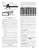
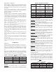
Limit Levels and Actions
The response of the system to the LAT/HPT sensors are shown in
Table 2. Cooling and HP limits are not adjustable. Looking at
Table 2, there are eight limit level index numbers, 0 through 7.
These represent the closeness of the actual LAT/HPT temperatures
to the final shutdown limit. 0 represents no limit challenge while
7 indicates a final shutdown of the equipment. Note that progres-
sive actions are taken by the control as the LAT/HPT limit is
approached. Each action progressively reduces the limit challenge
by increasing airflow. Normally, the system will stabilize at limit
level 1 or 2 because opening all closed dampers 2 or 4 positions
(out of 15) will reduce LAT to a level below its limit.
TABLE 2—LIMIT TEMPERATURE LEVELS AND ACTIONS
LIMIT LEVEL 01234567
Cooling Limit (40 deg) above 47 46 45 44 43 42 41 40
HP limit (115 deg) below 107 108 109 110 111 112 113 115
Heat Limit (130 deg) below 119 121 122 124 125 127 128 130
Heat Limit (145 deg) below 131 133 135 137 139 141 143 145
Heat Limit (160 deg) below 143 145 148 150 153 155 158 160
Heat Limit (175 deg) below 155 158 161 164 166 169 172 175
LIMIT ACTIONS
″Closed″ Damper Positions 02468101214
Allowed stages (1 stg) 11111110
Allowed Stages (2 stg) 22211110
Allowed stages (3 stg) 33322110
—6—