548J PACKAGED HEAT PUMP 3 TO 8.5 NOMINAL TONS Product Data C08515 (Optional hail guard shown.) the environmentally sound refrigerant This product has been designed and manufactured to meet Energy Star® criteria for energy efficiency. However, proper refrigerant charge and proper air flow are critical to achieve rated capacity and efficiency. Installation of this product should follow all manufacturer’s refrigerant charging and air flow instructions.
TABLE OF CONTENTS PAGE FEATURES AND BENEFITS . . . . . . . . . . . . . . . . . . . . 3 COOLING TABLES . . . . . . . . . . . . . . . . . . . . . . . . . . . 26 MODEL NUMBER NOMENCLATURE . . . . . . . . . . . . 4 STATIC PRESSURE TABLES . . . . . . . . . . . . . . . . . . . 35 FACTORY OPTIONS & ACCESSORIES . . . . . . . . . . . 5 FAN PERFORMANCE . . . . . . . . . . . . . . . . . . . . . . . . . 36 ARI CAPACITY RATING . . . . . . . . . . . . . . . . . . . . . . . 8 OUTDOOR AIR INTAKE & EXHAUST PERF . .
FEATURES AND BENEFITS S Up to 28% lighter than similar industry units. Lighter rooftops make easier replacement jobs. S 3-- 8.5 ton units fit on existing Bryant rooftop curbs making the utility connections the same. This saves time and money on replacement jobs. S Standardized components and layout. Standardized components and controls make service and stocking parts easier. S Scroll compressors on all units. This makes service, stocking parts, replacement, and trouble-- shooting easier.
MODEL NUMBER NOMENCLATURE 1 2 3 4 5 4 8 J P 0 ____________ 5 6 7 8 9 6 A 0 ______ 10 11 12 13 14 15 16 17 18 0 0 A 0 B 0 A A -- ________ ______ Unit Type Design Revision 548J = High Eff. Heat Pump --- = First Revision Voltage Packaging E = 460--- 3--- 60 A = Standard J = 208/230--- 1--- 60 B = LTL P = 208/230--- 3--- 60 Factory Installed Options T = 575--- 3--- 60 0A = None 548J Cooling Tons 04 = 3 Ton 07 = 6 Ton Outdoor Air Options 05 = 4 Ton 08 = 7.
FACTORY OPTIONS AND/OR ACCESSORIES Table 1 – FACTORY-- INSTALLED OPTIONS AND FIELD-- INSTALLED ACCESSORIES Cabinet Coil Options Condenser Protection Controls Economizers & Outdoor Air Dampers Economizer Sensors & IAQ Devices Electric Heat Indoor Motor & Drive Low Ambient Control Power Options Roof Curbs ITEM Thru--- the--- base electrical connections Cu/Cu indoor and/or outdoor coils Pre--- coated outdoor coils Premium, E--- coated outdoor coils Condenser coil hail guard (louvered design) Thermostats,
FACTORY OPTIONS AND/OR ACCESSORIES (cont.) Economizer (dry--bulb or enthalpy) Non--fused Disconnect Economizers save money. They bring in fresh, outside air for ventilation; and provide cool, outside air to cool your building. This is the preferred method of low-- ambient cooling. When coupled to CO2 sensors, Economizers can provide even more savings by coupling the ventilation air to only that amount required.
FACTORY OPTIONS AND/OR ACCESSORIES (cont.) Motormaster Head Pressure Controller Thru--the--Base Connections The Motormaster motor controller is a low ambient, head pressure controller kit that is designed to maintain the unit’s condenser head pressure during periods of low ambient cooling operation. This device should be used as an alternative to economizer free cooling not when economizer usage is either not appropriate or desired.
Table 2 – ARI COOLING RATING TABLES 548J* 04A 05A 06A 07A 08D 09D NOMINAL CAPACITY (TONS) 3 4 5 6 7.5 8.5 NET COOLING CAPACITY (BTUH) 37,000 47,000 61,500 70,000 88,000 99,000 COOLING MODE TOTAL POWER (kW) 3.3 4.1 5.5 6.3 7.8 8.8 SEER EER IPLV 13.40** 13.10** 13.20** N/A N/A N/A 11.00 11.20 11.15 11.10 11.20 11.20 N/A N/A N/A N/A 12.40 12.40 548J NOTE: All AHRI ratings are based on 230, 460 and 575 volt. ** Electric Drive (direct drive) X13 5 speed/torque motor. SEER rating is 13.
Table 3 – MINIMUM - MAXIMUM AIRFLOWS ELECTRIC HEAT UNIT 548J*04 548J*05 548J*06 548J*07 548J*08 548J*09 COOLING MINIMUM 900 1200 1500 1800 2250 2550 ELECTRIC HEATERS MINIMUM MAXIMUM 900 1500 1200 2000 1500 2500 1800 3000 2250** 3750 2250** 4250 MAXIMUM 1500 2000 2500 3000 3750 4250 **Minimum electric heat CFM exceptions : UNIT VOLTAGE HEATER kW UNIT CONFIGURATION 548J*08 548J*09 575 17.0 34.
548J*05 548J*06 548J*07 1 / 1 / Scroll 9 --- 8 / --42 / --Acutrol 630 / 505 27 / 44 1 / 1 / Scroll 10 --- 3 / --42 / --Acutrol 630 / 505 27 / 44 1 / 1 / Scroll 12 --- 13 / --42 / --Acutrol 630 / 505 27 / 44 1 / 1 / Scroll 16 --- 13 / --56 / --Acutrol 630 / 505 27 / 44 Cu / Al 3/8” RTPF 3 / 15 5.5 3/4” Cu / Al 3/8” RTPF 3 / 15 5.5 3/4” Cu / Al 3/8” RTPF 4/ 15 7.3 3/4” Cu / Al 3/8” RTPF 4/ 15 7.
7.5 - 8.5 TONS 548J*08 548J*09 # Circuits / # Comp. / Type Puronr refrig. (R--- 410A) charge per circuit A/B (lbs--- oz) Oil A/B (oz) Metering Device High--- pressure Trip / Reset (psig) Loss of Charge Pressure Trip / Reset (psig) Evap. Coil Material Coil type Rows / FPI Total Face Area (ft2) Condensate Drain Conn. Size Evap.
208/230---1---60 NOM. V ---PH ---HZ UNIT Table 7 – ELECTRIC HEAT - ELECTRICAL DATA IFM TYPE STD DD 208/230---3---60 548J*04 548J STD DD MED BD HIGH BD 460---3---60 STD DD MED BD HIGH BD ELECTRIC HEATER PART NUMBER CRHEATERXXXXXX NOM PWR (kW) APP PWR (kW) 101A00 102A00 103B00 104B00 102A00,102A00 101A00 102A00 103B00 104B00 105A00 101A00 102A00 103B00 104B00 105A00 101A00 102A00 103B00 104B00 105A00 106A00 107A00 108A00 109A00 106A00 107A00 108A00 109A00 106A00 107A00 108A00 109A00 4.4 6.
IFM TYPE STD DD 208/230---3---60 548J*05 STD DD MED BD HIGH BD 460---3---60 STD DD MED BD HIGH BD ELECTRIC HEATER PART NUMBER CRHEATERXXXXXX 101A00 103B00 102A00,102A00 103B00,103B00 104B00,104B00 102A00 103B00 105A00 104B00,104B00 102A00 103B00 105A00 104B00,104B00 102A00 103B00 105A00 104B00,104B00 106A00 108A00 109A00 108A00,108A00 106A00 108A00 109A00 108A00,108A00 106A00 108A00 109A00 108A00,108A00 NOM PWR (kW) 4.4 8.7 13.0 17.4 21.0 6.5 8.7 16.0 21.0 6.5 8.7 16.0 21.0 6.5 8.7 16.0 21.0 6.
208/230---1---60 NOM. V ---PH ---HZ UNIT Table 7 - (cont.
IFM TYPE 208/230--- 3--- 60 STD MED 548J*07 HIGH 460--- 3--- 60 STD MED HIGH ELECTRIC HEATER PART NUMBER CRHEATERXXXXXX 102A00 104B00 105A00 104B00,104B00 104B00,105A00 102A00 104B00 105A00 104B00,104B00 104B00,105A00 102A00 104B00 105A00 104B00,104B00 104B00,105A00 106A00 108A00 109A00 108A00,108A00 108A00,109A00 106A00 108A00 109A00 108A00,108A00 108A00,109A00 106A00 108A00 109A00 108A00,108A00 108A00,109A00 NOM PWR (kW) 6.5 10.5 16.0 21.0 26.5 6.5 10.5 16.0 21.0 26.5 6.5 10.5 16.0 21.0 26.5 6.
NOM. V ---PH ---HZ UNIT Table 7 - (cont.
IFM TYPE 208/230--- 3--- 60 STD MED STD 460--- 3--- 60 548J*09 (2---STAGE COOL) HIGH MED 575--- 3--- 60 HIGH STD MED HIGH ELECTRIC HEATER PART NUMBER CRHEATERXXXXXX 117A00 110A00 111A00 112A00 112A00,117A00 117A00 110A00 111A00 112A00 112A00,117A00 117A00 110A00 111A00 112A00 112A00,117A00 116A00 113A00 114A00 115A00 114A00,116A00 116A00 113A00 114A00 115A00 114A00,116A00 116A00 113A00 114A00 115A00 114A00,116A00 118A00 119A00 118A00 119A00 118A00 119A00 NOM PWR (kW) 10.4 16.0 24.8 32.0 42.
548J WEIGHTS & DIMENSIONS C09018 Fig.
548J WEIGHTS & DIMENSIONS (cont.) C09019 Fig. 2 -- Dimensions 548J 04--07 C D B A C08337 Fig. 3 -- Service Clearance LOC A B C D DIMENSION 48” (1219 mm) 18” (457 mm) 18” (457 mm) 12” (305 mm) 42” (1067 mm) 36” (914 mm) Special 36” (914 mm) 18” (457 mm) 42” (1067 mm) 36” (914 mm) CONDITION Unit disconnect is mounted on panel No disconnect, convenience outlet option Recommended service clearance Minimum clearance Surface behind servicer is grounded (e.g.
WEIGHTS & DIMENSIONS (cont.) ROOFCURB ACCESSORY 548J*04-07A 548J 1’ - 2” CRRFCURB001A01 [356] CRRFCURB002A01 2’ - 0” [610] UNIT SIZE C08560 Fig.
548J WEIGHTS & DIMENSIONS (cont.) Vertical Connections / Economizer Horizontal Connections / Economizer C08679 Fig.
548J WEIGHTS & DIMENSIONS (cont.) C08680 Fig. 6 -- Dimensions 548J 08--09 C D B A C08337 Fig. 7 -- Service Clearance LOC A B C D DIMENSION 48” (1219 mm) 18” (457 mm) 18” (457 mm) 12” (305 mm) 42” (1067 mm) 36” (914 mm) Special 36” (914 mm) 18” (457 mm) 42” (1067 mm) 36” (914 mm) CONDITION Unit disconnect is mounted on panel No disconnect, convenience outlet option Recommended service clearance Minimum clearance Surface behind servicer is grounded (e.g.
WEIGHTS & DIMENSIONS (cont.) 1’ - 2” CRRFCURB003A01 [356] CRRFCURB004A01 2’ - 0” [610] UNIT SIZE 548J08, 09 548J ROOFCURB ACCESSORY C08561 Fig.
APPLICATION DATA Min operating ambient temp (cooling): Sizing a rooftop In mechanical cooling mode, your Bryant rooftop can safely operate down to an outdoor ambient temperature of 25_F (-- 4_C). It is possible to provide cooling at lower outdoor ambient temperatures by using less outside air, economizers, and/or accessory low ambient kits. Bigger isn’t necessarily better. While an air conditioner needs to have enough capacity to meet the load, it doesn’t need excess capacity.
SELECTION PROCEDURE (WITH 548J*07 EXAMPLE) (Selection software by Bryant saves time by performing many of the steps below.) II. Determine cooling and heating loads. Given: Mixed Air Drybulb 80_F (27_C) Mixed Air Wetbulb 67_F (19_C) Ambient Drybulb 95_F (35_C) 65.0 MBH TCLoad 46.0 MBH SHCLoad 45.0 MBH HCLoad Outdoor-Air Winter Design Temp 0_F (-- 18_C) Indoor-Air Winter Design Temp 70_F (21_C) Vertical Supply Air 2100 CFM External Static Pressure 0.66 in.
Table 8 – COOLING CAPACITIES 548J*04 58 EAT (wb) 900 Cfm 62 67 72 76 EAT (wb) 1050 Cfm 62 67 72 76 58 EAT (wb) 1200 Cfm 62 67 72 76 58 EAT (wb) 1350 Cfm 62 67 72 76 58 EAT (wb) 62 1500 Cfm 548J 58 67 72 76 LEGEND --Cfm EAT(db) EAT(wb) SHC TC ------------- THC SHC THC SHC THC SHC THC SHC THC SHC THC SHC THC SHC THC SHC THC SHC THC SHC THC SHC THC SHC THC SHC THC SHC THC SHC THC SHC THC SHC THC SHC THC SHC THC SHC THC SHC THC SHC THC SHC THC SHC THC SHC 75 31.4 27.1 33.5 24.8 38.0 21.
548J*05 58 EAT (wb) 1200 Cfm 62 67 72 76 58 EAT (wb) 1400 Cfm 62 67 72 76 58 EAT (wb) 1600 Cfm 62 67 72 76 58 EAT (wb) 1800 Cfm 62 67 72 76 58 EAT (wb) 2000 Cfm 62 67 72 76 LEGEND --Cfm EAT(db) EAT(wb) SHC TC ------------- TC SHC TC SHC TC SHC TC SHC TC SHC TC SHC TC SHC TC SHC TC SHC TC SHC TC SHC TC SHC TC SHC TC SHC TC SHC TC SHC TC SHC TC SHC TC SHC TC SHC TC SHC TC SHC TC SHC TC SHC TC SHC 75 41.7 36.5 44.1 33.7 48.8 28.2 53.2 22.3 ----44.1 38.1 45.8 36.2 50.2 29.7 54.4 22.9 ----46.
Table 10 – COOLING CAPACITIES 548J*06 58 EAT (wb) 1500 Cfm 62 67 72 76 EAT (wb) 1750 Cfm 62 67 72 76 58 EAT (wb) 2000 Cfm 62 67 72 76 58 EAT (wb) 2250 Cfm 62 67 72 76 58 EAT (wb) 62 2500 Cfm 548J 58 67 72 76 LEGEND --Cfm EAT(db) EAT(wb) SHC TC ------------- TC SHC TC SHC TC SHC TC SHC TC SHC TC SHC TC SHC TC SHC TC SHC TC SHC TC SHC TC SHC TC SHC TC SHC TC SHC TC SHC TC SHC TC SHC TC SHC TC SHC TC SHC TC SHC TC SHC TC SHC TC SHC 75 52.7 46.2 55.5 42.8 61.7 35.6 68.0 27.9 ----56.0 48.
548J*07 58 EAT (wb) 1800 Cfm 62 67 72 76 58 EAT (wb) 2100 Cfm 62 67 72 76 58 EAT (wb) 2400 Cfm 62 67 72 76 58 EAT (wb) 2700 Cfm 62 67 72 76 58 EAT (wb) 3000 Cfm 62 67 72 76 LEGEND --Cfm EAT(db) EAT(wb) SHC TC ------------- TC SHC TC SHC TC SHC TC SHC TC SHC TC SHC TC SHC TC SHC TC SHC TC SHC TC SHC TC SHC TC SHC TC SHC TC SHC TC SHC TC SHC TC SHC TC SHC TC SHC TC SHC TC SHC TC SHC TC SHC TC SHC 75 61.1 53.3 64.1 49.6 70.8 40.7 77.4 31.1 ----64.6 55.5 66.1 53.4 72.8 43.1 79.2 31.9 ----67.
Table 12 – COOLING CAPACITIES 548J*08 58 EAT (wb) 2250Cfm 62 67 72 76 EAT (wb) 2625 Cfm 62 67 72 76 58 EAT (wb) 3000 Cfm 62 67 72 76 58 EAT (wb) 3375 Cfm 62 67 72 76 58 EAT (wb) 62 3750 Cfm 548J 58 67 72 76 LEGEND --Cfm EAT(db) EAT(wb) SHC TC ------------- TC SHC TC SHC TC SHC TC SHC TC SHC TC SHC TC SHC TC SHC TC SHC TC SHC TC SHC TC SHC TC SHC TC SHC TC SHC TC SHC TC SHC TC SHC TC SHC TC SHC TC SHC TC SHC TC SHC TC SHC TC SHC 75 77.4 66.9 81.8 60.6 90.6 50.4 99.4 39.6 ----81.8 70.
548J*09 58 EAT (wb) 2550 Cfm 62 67 72 76 58 EAT (wb) 2975 Cfm 62 67 72 76 58 EAT (wb) 3400 Cfm 62 67 72 76 58 EAT (wb) 3825 Cfm 62 67 72 76 58 EAT (wb) 4250 Cfm 62 67 72 76 LEGEND --Cfm EAT(db) EAT(wb) SHC TC ------------- TC SHC TC SHC TC SHC TC SHC TC SHC TC SHC TC SHC TC SHC TC SHC TC SHC TC SHC TC SHC TC SHC TC SHC TC SHC TC SHC TC SHC TC SHC TC SHC TC SHC TC SHC TC SHC TC SHC TC SHC TC SHC 75 91.1 79.4 96.0 72.7 106.4 60.4 117.3 47.4 ----96.5 84.1 98.2 78.1 109.5 64.1 120.6 49.
Table 14 – HEATING CAPACITIES 3 TONS 548J*04 RETURN AIR (°F db) CFM (STANDARD AIR) 900 55 1200 1500 900 70 1200 548J 1500 900 80 1200 1500 Capacity Int. Cap. Capacity Int. Cap. Capacity Int. Cap. Capacity Int. Cap. Capacity Int. Cap. Capacity Int. Cap. Capacity Int. Cap. Capacity Int. Cap. Capacity Int. Cap. TEMPERATURE AIR ENTERING OUTDOOR COIL (°F db at 70% rh) ---10 0 10 17 30 40 47 50 60 11.6 10.7 12.0 11.1 12.6 11.6 9.8 9.0 10.1 9.3 10.8 10.0 8.3 7.7 8.6 8.0 9.3 8.6 15.1 13.9 15.
Table 16 – HEATING CAPACITY 5 TONS 548J*06 CFM (STANDARD AIR) 1500 55 2000 2500 1500 70 2000 2500 1500 80 2000 2500 Capacity Int. Cap. Capacity Int. Cap. Capacity Int. Cap. Capacity Int. Cap. Capacity Int. Cap. Capacity Int. Cap. Capacity Int. Cap. Capacity Int. Cap. Capacity Int. Cap. TEMPERATURE AIR ENTERING OUTDOOR COIL (°F DB AT 70% RH) ---10 0 10 17 30 40 47 50 60 22.7 21.0 22.8 21.1 24.2 22.4 19.9 18.4 20.1 18.6 21.5 19.9 17.6 16.3 17.8 16.5 19.3 17.8 28.3 26.1 28.5 26.2 30.0 27.
Table 18 – HEATING CAPACITY 7.5 TONS 548J*08 RETURN AIR (°F db) CFM (STANDARD AIR) 2250 55 3000 3750 2250 70 3000 548J 3750 2250 80 3000 3750 Capacity Int. Cap. Capacity Int. Cap. Capacity Int. Cap. Capacity Int. Cap. Capacity Int. Cap. Capacity Int. Cap. Capacity Int. Cap. Capacity Int. Cap. Capacity Int. Cap. TEMPERATURE AIR ENTERING OUTDOOR COIL (°F db at 70% rh) ---10 25.9 23.9 27.4 25.3 31.0 28.6 22.5 20.8 24.1 22.3 27.8 25.7 0 34.6 31.8 36.2 33.4 40.0 36.8 31.5 29.0 33.3 30.6 37.1 34.
Table 20 – STATIC PRESSURE ADDERS (Factory Options and/or Accessories) Economizer CFM (in. wg) Vertical Economizer Horizontal Economizer 600 800 1000 3 --- 6 TONS 1250 1500 1750 2000 2250 2500 2750 3000 0.01 0.02 0.04 0.05 0.07 0.09 0.12 0.15 0.18 0.22 0.26 0.02 0.03 0.04 0.06 0.08 0.10 0.13 0.15 0.18 0.23 0.28 2250 2500 2750 3000 3250 7.5 --- 8.5 TONS 3500 3750 4000 4250 4500 4750 5000 5250 5500 5750 6000 0.06 0.08 0.09 0.12 0.13 0.15 0.17 0.20 0.
FAN PERFORMANCE Table 21 – 548J*04 ELECTRIC DRIVE, X13 MOTOR, 3 TON HORIZONTAL SUPPLY SPEED (TORQUE) TAP 548J 1 2 3 4 5 CFM ESP BHP 900 975 1050 1125 1200 1275 1350 1425 1500 900 975 1050 1125 1200 1275 1350 1425 1500 900 975 1050 1125 1200 1275 1350 1425 1500 900 975 1050 1125 1200 1275 1350 1425 1500 900 975 1050 1125 1200 1275 1350 1425 1500 0.70 0.60 0.50 0.39 0.29 0.21 0.12 0.03 --0.85 0.76 0.66 0.55 0.46 0.36 0.27 0.17 0.07 1.02 0.94 0.86 0.79 0.71 0.61 0.51 0.40 0.29 1.12 1.06 1.00 0.95 0.
FAN PERFORMANCE (cont.) SPEED (TORQUE) TAP 1 2 3 4 5 CFM ESP BHP 1200 1300 1400 1500 1600 1700 1800 1900 2000 1200 1300 1400 1500 1600 1700 1800 1900 2000 1200 1300 1400 1500 1600 1700 1800 1900 2000 1200 1300 1400 1500 1600 1700 1800 1900 2000 1200 1300 1400 1500 1600 1700 1800 1900 2000 0.75 0.63 0.48 0.33 0.19 0.05 ------0.97 0.88 0.77 0.64 0.50 0.36 0.21 0.06 --0.98 0.91 0.82 0.71 0.58 0.45 0.31 0.16 0.03 0.98 0.92 0.86 0.79 0.70 0.62 0.52 0.37 0.21 1.02 0.97 0.92 0.87 0.82 0.77 0.71 0.65 0.
FAN PERFORMANCE (cont.) Table 25 – 548J*06 ELECTRIC DRIVE, X13 MOTOR, 5 TON HORIZONTAL SUPPLY SPEED (TORQUE) TAP 548J 1 2 3 4 5 CFM ESP BHP 1500 1625 1750 1875 2000 2125 2250 2375 2500 1500 1625 1750 1875 2000 2125 2250 2375 2500 1500 1625 1750 1875 2000 2125 2250 2375 2500 1500 1625 1750 1875 2000 2125 2250 2375 2500 1500 1625 1750 1875 2000 2125 2250 2375 2500 1.19 1.01 0.82 0.60 0.38 0.16 ------1.40 1.25 1.08 0.90 0.67 0.44 0.20 ----1.41 1.28 1.13 0.96 0.74 0.51 0.27 0.02 --1.44 1.35 1.24 1.
FAN PERFORMANCE (cont.) CFM 900 975 1050 1125 1200 1275 1350 1425 1500 BHP 0.13 0.15 0.18 0.20 0.23 0.26 0.30 0.34 0.38 BHP 0.47 0.50 0.53 0.57 0.61 0.65 0.70 0.75 0.80 RPM 999 1015 1030 1047 1064 1082 1100 1119 1138 BHP 0.77 0.80 0.84 0.88 0.92 0.97 1.02 1.08 1.14 AVAILABLE EXTERNAL STATIC PRESSURE (IN. WG) 1.4 1.6 1.8 BHP RPM BHP RPM 0.93 1220 1.11 1284 0.97 1233 1.15 1297 1.01 1247 1.19 1311 1.05 1261 1.23 1325 1.10 1276 1.28 1339 1.15 1292 1.33 1354 1.20 1308 1.39 1370 1.26 1325 1.45 1386 1.
FAN PERFORMANCE (cont.) Table 29 – 548J*05 CFM 548J 1200 1300 1400 1500 1600 1700 1800 1900 2000 BHP 0.23 0.28 0.33 0.38 0.45 0.52 0.60 0.69 0.78 BHP 0.61 0.67 0.73 0.80 0.89 0.97 1.07 1.18 1.29 RPM 1064 1088 1113 1138 1165 1192 1221 1250 1280 BHP 0.92 0.99 1.06 1.14 1.23 1.33 1.44 1.55 1.68 AVAILABLE EXTERNAL STATIC PRESSURE (IN. WG) 1.4 1.6 1.8 BHP RPM BHP RPM 1.10 1276 1.28 1339 1.16 1297 1.35 1360 1.24 1319 1.43 1381 1.33 1342 1.52 1403 1.42 1365 1.62 1425 1.52 1390 1.72 1449 1.63 1415 1.
FAN PERFORMANCE (cont.) CFM 1500 1625 1750 1875 2000 2125 2250 2375 2500 RPM 840 876 912 950 988 1027 1067 1107 1148 BHP 0.75 0.84 0.94 1.05 1.18 1.31 1.46 1.63 1.81 RPM 1101 1131 1162 1194 1226 1260 1294 1329 1364 RPM 1239 1267 1296 1326 1357 1388 1420 1453 1487 AVAILABLE EXTERNAL STATIC PRESSURE (IN. WG) 1.4 1.6 1.8 BHP RPM BHP RPM 1.23 1302 1.40 1361 1.34 1329 1.52 1388 1.46 1358 1.65 1416 1.60 1387 1.79 1445 1.74 1417 1.95 1474 1.90 1447 2.11 1504 2.08 1479 2.29 1534 2.27 1511 2.49 1566 2.
FAN PERFORMANCE (cont.) Table 33 – 548J*07 CFM 1800 1950 2100 2250 2400 2550 2700 2850 3000 548J RPM 927 973 1019 1067 1115 1164 1214 1264 1315 BHP 0.98 1.13 1.29 1.46 1.66 1.88 2.12 2.39 2.68 RPM 1174 1213 1253 1294 1336 1379 1422 1467 1512 RPM 1308 1345 1382 1420 1460 1500 1541 ----- AVAILABLE EXTERNAL STATIC PRESSURE (IN. WG) 1.4 1.6 1.8 BHP RPM BHP RPM 1.51 1369 1.70 1427 1.68 1405 1.88 1462 1.87 1441 2.08 1498 2.08 1479 2.29 1534 2.31 1517 2.53 1572 2.55 1557 2.79 --2.
FAN PERFORMANCE (cont.) CFM 2250 2438 2625 2813 3000 3188 3375 3563 3750 BHP ----0.40 0.47 0.55 0.65 0.75 0.86 0.99 BHP 0.66 0.73 0.82 0.91 1.02 1.13 1.26 1.39 1.54 RPM 725 733 743 753 765 779 793 808 824 BHP 0.94 1.03 1.13 1.24 1.36 1.49 1.63 1.78 1.94 AVAILABLE EXTERNAL STATIC PRESSURE (IN. WG) 1.4 1.6 1.8 RPM BHP RPM BHP RPM 847 1.09 903 1.25 957 852 1.19 907 1.36 959 858 1.30 911 1.47 963 865 1.41 917 1.59 967 874 1.54 925 1.72 974 884 1.68 933 1.87 981 895 1.82 943 2.02 990 907 1.98 954 2.
FAN PERFORMANCE (cont.) Table 37 – 548J*09 CFM 2550 2763 2975 3188 3400 3613 3825 4038 4250 548J BHP 0.39 0.47 0.57 0.68 0.80 0.94 1.09 1.26 1.45 BHP 0.80 0.91 1.03 1.17 1.31 1.48 1.66 1.85 2.07 RPM 747 760 774 789 806 824 843 864 885 BHP 1.11 1.24 1.37 1.53 1.69 1.87 2.07 2.28 2.51 AVAILABLE EXTERNAL STATIC PRESSURE (IN. WG) 1.4 1.6 1.8 RPM BHP RPM BHP RPM 863 1.28 916 1.45 968 871 1.41 924 1.59 974 882 1.55 932 1.74 981 894 1.71 943 1.90 990 907 1.88 955 2.09 1001 922 2.07 968 2.28 1013 938 2.
FAN PERFORMANCE (cont.) 3 phase 3 phase 3 phase 3 phase 3 phase 3 phase 09 08 07 06 05 04 UNIT MOTOR/DRIVE COMBO MOTOR PULLEY TURNS OPEN 2 2.5 3 3.5 0 0.5 1 1.5 4 4.
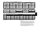
ECONOMIZER, BAROMETRIC RELIEF AND PE PERFORMANCE 2500 Horizontal Economizers 2000 1500 RELIEF FLOW (CFM) RELIEF FLOW (CFM) 2500 3-6 Ton 7.5-8.5 Ton 1000 500 Vertical Economizers 2000 1500 3 - 6 Ton 7.5 - 8.5 Ton 1000 500 0 0 0 0.05 0.1 0.15 0.2 0.25 0 0.3 0.05 0.1 0.15 0.2 0.25 0.3 RETURN DUCT STATIC PRESS URE (in. wg) RETURN DUCT STATIC PRESS URE (in. wg) C09028 C09031 30 Fig.
ELECTRICAL INFORMATION V-- Ph-- Hz 1-- Stage Cooling VOLTAGE RANGE COMP (ea) OFM (ea) IFM MIN MAX RLA LRA WATTS FLA TYPE 208--1--60 230--1--60 187 187 253 253 17.9 17.9 112 112 190 190 0.9 0.9 208--3--60 187 253 13.2 88 190 0.9 230--3--60 187 253 13.2 88 190 0.9 460--3--60 414 506 6.0 44 190 0.5 575--3--60 518 633 NA NA 190 0.
ELECTRICAL INFORMATION (cont.) Table 43 – 548J*07 V ---Ph---Hz VOLTAGE RANGE MIN 548J 1-- Stage Cooling MAX COMP (ea) RLA LRA OFM (ea) WATTS IFM FLA 208--- 3--- 60 187 253 19.0 123 325 1.5 230--- 3--- 60 187 253 19.0 123 325 1.5 460--- 3--- 60 414 506 9.7 62 325 0.8 575--- 3--- 60 518 633 7.4 50 325 0.
ELEC. HTR IFM TYPE 208/230---3---60 MCA MOCP DISC. SIZE FLA LRA MCA MOCP DISC. SIZE FLA LRA DD--- STD 30.7 50.6/53.6 60.1/64.6 69.9/76.1 78.1/85.4 89.3/98.4 24.8 36.3/38.1 41.8/44.3 47.4/50.9 52.2/56.4 66.6/72.9 22.6 34.1/35.9 39.6/42.1 45.2/48.7 50.0/54.2 64.4/70.7 22.6 34.1/35.9 39.6/42.1 45.2/48.7 50.0/54.2 64.4/70.7 16.0 25.0 29.3 33.3 37.0 10.6 19.6 23.9 27.9 31.6 10.6 19.6 23.9 27.9 31.6 5.
208/230---1---60 NOM. V ---PH ---HZ UNIT Table 46 – (cont.) MCA/MOCP DETERMINATION WITHOUT C.O. OR UNPWRD C.O. ELEC. HTR IFM TYPE 208/230---3---60 460---3---60 MCA MOCP DISC. SIZE FLA LRA MCA MOCP DISC. SIZE FLA LRA 36.2 56.0/59.0 75.4/81.5 94.8/103.9 114.7/126.8 130.9/145.5 26.0 43.0/45.5 48.7/52.2 67.8/74.2 80.8/89.2 23.8 40.8/43.3 46.5/50.0 65.6/72.0 78.6/87.0 23.8 40.8/43.3 46.5/50.0 65.6/72.0 78.6/87.0 16.5 25.5 33.8 37.5 51.1 11.2 20.2 28.4 32.2 45.8 11.2 20.2 28.4 32.2 45.
ELEC. HTR IFM TYPE 208/230---3---60 FLA MCA MOCP WITH P.E. DISC. SIZE FLA LRA MCA MOCP DISC. SIZE FLA LRA --23.5/27.1 31.4/36.3 46.9/54.2 62.8/72.5 75.8/87.5 --13.6/15.6 21.9/25.3 33.4/38.5 43.8/50.5 55.2/63.8 --13.6/15.6 21.9/25.3 33.4/38.5 43.8/50.5 55.2/63.8 --13.6/15.6 21.9/25.3 33.4/38.5 43.8/50.5 55.2/63.8 --7.2 13.8 16.8 27.7 30.7 --7.2 13.8 16.8 27.7 30.7 --7.2 13.8 16.8 27.7 30.7 41.7 71.0/75.5 80.9/87.0 100.3/109.4 120.2/132.3 136.4/151.0 28.4 45.4/47.9 55.8/60.0 70.2/76.5 83.2/91.
NOM. V ---PH ---HZ UNIT Table 46 – (cont.) MCA/MOCP DETERMINATION WITHOUT C.O. OR UNPWRD C.O. ELEC. HTR IFM TYPE 548J 208/230---3---60 STD MED 548J*07 HIGH 460---3---60 STD MED 575---3---60 HIGH WITHOUT C.O. or UNPWR C.O. WITHOUT P.E. Nom (kW) FLA MCA MOCP WITH P.E. DISC. SIZE FLA LRA MCA MOCP DISC. SIZE FLA LRA --4.9/6.5 7.9/10.5 12.0/16.0 15.8/21.0 19.9/26.5 --4.9/6.5 7.9/10.5 12.0/16.0 15.8/21.0 19.9/26.5 --4.9/6.5 7.9/10.5 12.0/16.0 15.8/21.0 19.9/26.5 --6.0 11.5 14.0 23.0 25.
ELEC. HTR IFM TYPE 208/230---3---60 STD MED HIGH 460---3---60 548J*08 STD MED HIGH 575---3---60 STD MED HIGH WITHOUT C.O. or UNPWR C.O. WITHOUT P.E. Nom (kW) --7.8/10.4 12.0/16.0 18.6/24.8 24.0/32.0 31.8/42.4 --7.8/10.4 12.0/16.0 18.6/24.8 24.0/32.0 31.8/42.4 --7.8/10.4 12.0/16.0 18.6/24.8 24.0/32.0 31.8/42.4 --13.9 16.5 27.8 33.0 41.7 --13.9 16.5 27.8 33.0 41.7 --13.9 16.5 27.8 33.0 41.7 --17.0 34.0 --17.0 34.0 --17.0 34.0 FLA --21.7/25.0 33.4/38.5 51.7/59.7 66.7/77.0 88.4/102.0 --21.7/25.
NOM. V ---PH ---HZ UNIT Table 46 – (cont.) MCA/MOCP DETERMINATION WITHOUT C.O. OR UNPWRD C.O. ELEC. HTR IFM TYPE 548J 208/230---3---60 STD MED HIGH 460---3---60 548J*09 STD MED HIGH 575---3---60 STD MED HIGH WITHOUT C.O. or UNPWR C.O. WITHOUT P.E. Nom (kW) --7.8/10.4 12.0/16.0 18.6/24.8 24.0/32.0 31.8/42.4 --7.8/10.4 12.0/16.0 18.6/24.8 24.0/32.0 31.8/42.4 --7.8/10.4 12.0/16.0 18.6/24.8 24.0/32.0 31.8/42.4 --13.9 16.5 27.8 33.0 41.7 --13.9 16.5 27.8 33.0 41.7 --13.9 16.5 27.8 33.0 41.
ELEC. HTR IFM TYPE 208/230---3---60 MCA MOCP DISC. SIZE FLA LRA MCA MOCP DISC. SIZE FLA LRA 35.5 55.4/58.4 64.9/69.4 74.7/80.9 82.9/90.2 94.1/103.2 29.6 41.1/42.9 46.6/49.1 52.2/55.7 57.0/61.2 71.4/77.7 27.4 38.9/40.7 44.4/46.9 50.0/53.5 54.8/59.0 69.2/75.5 27.4 38.9/40.7 44.4/46.9 50.0/53.5 54.8/59.0 69.2/75.5 18.2 27.2 31.5 35.5 39.2 12.8 21.8 26.1 30.1 33.8 12.8 21.8 26.1 30.1 33.
208/230---1---60 NOM. V ---PH ---HZ UNIT Table 47– (cont.) MCA/MOCP DETERMINATION WITH PWRD C.O. ELEC. HTR IFM TYPE 208/230---3---60 460---3---60 MCA MOCP DISC. SIZE FLA LRA MCA MOCP DISC. SIZE FLA LRA 41 60.8/63.8 80.2/86.3 99.6/108.7 119.5/131.6 135.7/150.3 30.8 47.8/50.3 53.5/57.0 72.6/79.0 85.6/94.0 28.6 45.6/48.1 51.3/54.8 70.4/76.8 83.4/91.8 28.6 45.6/48.1 51.3/54.8 70.4/76.8 83.4/91.8 18.7 27.7 36.0 39.7 53.3 13.4 22.4 30.6 34.4 48.0 13.4 22.4 30.6 34.4 48.
ELEC. HTR IFM TYPE 208/230---3---60 FLA MCA MOCP WITH P.E. DISC. SIZE FLA LRA MCA MOCP DISC. SIZE FLA LRA --23.5/27.1 31.4/36.3 46.9/54.2 62.8/72.5 75.8/87.5 --13.6/15.6 21.9/25.3 33.4/38.5 43.8/50.5 55.2/63.8 --13.6/15.6 21.9/25.3 33.4/38.5 43.8/50.5 55.2/63.8 --13.6/15.6 21.9/25.3 33.4/38.5 43.8/50.5 55.2/63.8 --7.2 13.8 16.8 27.7 30.7 --7.2 13.8 16.8 27.7 30.7 --7.2 13.8 16.8 27.7 30.7 46.5 75.8/80.3 85.7/91.8 105.1/114.2 125.0/137.1 141.2/155.8 33.2 50.2/52.7 60.6/64.8 75.0/81.3 88.0/96.
NOM. V ---PH ---HZ UNIT Table 47 – (cont.) MCA/MOCP DETERMINATION WITH PWRD C.O. ELECTRIC HEATER IFM TYPE 548J 208/230---3---60 STD MED 548J*07 HIGH 460---3---60 STD MED 575---3---60 HIGH WITH PWRD C.O. WITHOUT P.E. Nom (kW) FLA MCA MOCP WITH P.E. DISC. SIZE FLA LRA MCA MOCP DISC. SIZE FLA LRA --4.9/6.5 7.9/10.5 12.0/16.0 15.8/21.0 19.9/26.5 --4.9/6.5 7.9/10.5 12.0/16.0 15.8/21.0 19.9/26.5 --4.9/6.5 7.9/10.5 12.0/16.0 15.8/21.0 19.9/26.5 --6.0 11.5 14.0 23.0 25.5 --6.0 11.5 14.
ELECTRIC HEATER IFM TYPE 208/230---3---60 STD MED HIGH 460---3---60 548J*08 STD MED HIGH 575---3---60 STD MED HIGH WITH PWRD C.O. WITHOUT P.E. Nom (kW) --7.8/10.4 12.0/16.0 18.6/24.8 24.0/32.0 31.8/42.4 --7.8/10.4 12.0/16.0 18.6/24.8 24.0/32.0 31.8/42.4 --7.8/10.4 12.0/16.0 18.6/24.8 24.0/32.0 31.8/42.4 --13.9 16.5 27.8 33.0 41.7 --13.9 16.5 27.8 33.0 41.7 --13.9 16.5 27.8 33.0 41.7 --17.0 34.0 --17.0 34.0 --17.0 34.0 FLA --21.7/25.0 33.4/38.5 51.7/59.7 66.7/77.0 88.4/102.0 --21.7/25.0 33.
NOM. V ---PH ---HZ UNIT Table 47 – (cont.) MCA/MOCP DETERMINATION WITH PWRD C.O. ELECTRIC HEATER IFM TYPE 548J 208/230---3---60 STD MED HIGH 460---3---60 548J*09 STD MED HIGH 575---3---60 STD MED HIGH WITH PWRD C.O. WITHOUT P.E. Nom (kW) --7.8/10.4 12.0/16.0 18.6/24.8 24.0/32.0 31.8/42.4 --7.8/10.4 12.0/16.0 18.6/24.8 24.0/32.0 31.8/42.4 --7.8/10.4 12.0/16.0 18.6/24.8 24.0/32.0 31.8/42.4 --13.9 16.5 27.8 33.0 41.7 --13.9 16.5 27.8 33.0 41.7 --13.9 16.5 27.8 33.0 41.7 --17.0 34.0 --17.0 34.
548J TYPICAL WIRING DIAGRAMS C09063 Fig.
548J C09065 Fig.
548J C09067 Fig.
Fig.
Fig.
SEQUENCE OF OPERATION Cooling, unit without economizer When thermostat calls for cooling, terminals G and Y1 are energized. The indoor-fan contactor (IFC), reversing valve solenoid (RVS) and compressor contactor are energized and indoor-fan motor, compressor, and outdoor fan starts. The outdoor fan motor runs continuously while unit is cooling. 548J Heating, unit without economizer Upon a request for heating from the space thermostat, terminal W1 will be energized with 24V.
If the space thermostat is satisfied during a defrost cycle, the unit will continue in the Defrost mode until the time or temperature constraints are satisfied. Automatic changeover When the system selection switch is set at AUTO. position, unit automatically changes from heating operation to cooling operation when the temperature of the conditioned space rises to the cooling level setting.
GUIDE SPECIFICATIONS -- 548J*04--09 Note about this specification: Bryant created this specification in “Masterformat” as published by the Construction Specification Institute. Please feel free to copy this specification directly into your building specifications. Rooftop Packaged Heat Pump HVAC Guide Specifications 548J Size Range: 3 to 8.5 Nominal Tons This product has been designed and manufactured to meet Energy Star® criteria for energy efficiency.
23 09 33 Electric and Electronic Control System for HVAC 23 09 33.13 Decentralized, Rooftop Units: 23 09 33.13.A. General: 1. Shall be complete with self-- contained low-- voltage control circuit protected by a resettable circuit breaker on the 24-- v transformer side. Transformer shall have 75VA capability. 2. Shall utilize color-- coded wiring. 3.
23 40 13 Panel Air Filters 23 40 13.13 Decentralized, Rooftop Units: 23 40 13.13.A. Standard filter section 1. Shall consist of factory-- installed, low velocity, throwaway 2-- in. thick fiberglass filters of commercially available sizes. 2. Unit shall use only one filter size. Multiple sizes are not acceptable. 3. Filters shall be accessible through an access panel with “no-- tool” removal as described in the unit cabinet section of this specification (23 81 19.13.H).
548J 5. Unit shall be factory configured for vertical supply & return configurations. 6. Unit shall be field convertible from vertical to horizontal configuration 7. Unit shall be capable of mixed operation: vertical supply with horizontal return or horizontal supply with vertical return. 23 81 19.13.G. Electrical Requirements 1. Main power supply voltage, phase, and frequency must match those required by the manufacturer. 23 81 19.13.H. Unit Cabinet 1.
548J 2. Optional Pre-- coated aluminum-- fin condenser coils: on all models. a. Shall have a durable epoxy-- phenolic coating to provide protection in mildly corrosive coastal environments. b. Coating shall be applied to the aluminum fin stock prior to the fin stamping process to create an inert barrier between the aluminum fin and copper tube. c. Epoxy-- phenolic barrier shall minimize galvanic action between dissimilar metals. 3. Optional Copper-- fin evaporator and condenser coils: on all models. a.
548J 3. Shall consist of factory-- installed, low velocity, throw-- away 2-- in. thick fiberglass filters. 4. Filters shall be standard, commercially available sizes. 5. Only one size filter per unit is allowed. 23 81 19.13.M. Evaporator Fan and Motor 1. Evaporator fan motor: a. Shall have permanently lubricated bearings. b. Shall have inherent automatic-- reset thermal overload protection or circuit breaker. c.
548J n. Economizer controller shall accept a 2-- 10Vdc CO2 sensor input for IAQ/DCV control. In this mode, dampers shall modulate the outdoor-- air damper to provide ventilation based on the sensor input. o. Compressor lockout sensor shall open at 35_F (2_C) and closes at 50_F (10_C). p. Actuator shall be direct coupled to economizer gear. No linkage arms or control rods shall be acceptable. q.
548J 9. Fan/Filter Status Switch: a. Switch shall provide status of indoor evaporator fan (ON/OFF) or filter (CLEAN/DIRTY). b. Status shall be displayed either over communication bus (when used with direct digital controls) or with an indicator light at the thermostat. 10. Propeller Power Exhaust: a. Power exhaust shall be used in conjunction with an integrated economizer. b. Independent modules for vertical or horizontal return configurations shall be available. c.
548J (2.) Heater assemblies are provided with integral fusing for protection of internal heater circuits not exceeding 48 amps each. Auto reset thermo limit controls, magnetic heater contactors (24V coil) and terminal block all mounted in electric heater control box (minimum 18 ga galvanized steel) attached to end of heater assembly. E2009 Bryant Heating & Cooling Systems D 7310 W. Morris St. D Indianapolis, IN 46231 Printed in U.S.A.