T6--PAC, T6--PHP, T6--NAC, T6--NHP PREFERREDt SERIES AC / HP THERMOSTAT Installation Instructions A07045 Programmable Control A07044 Non ---Programmable Control NOTE: Read the entire instruction manual before starting the installation.
TABLE OF CONTENTS PAGE SAFETY CONSIDERATIONS . . . . . . . . . . . . . . . . . . . . . . . . . . . . . . . . . . . . 2 INTRODUCTION . . . . . . . . . . . . . . . . . . . . . . . . . . . . . . . . . . . . . . . . . . . . . . 3 INSTALLATION CONSIDERATIONS . . . . . . . . . . . . . . . . . . . . . . . . . . . . . . 4 INSTALLATION . . . . . . . . . . . . . . . . . . . . . . . . . . . . . . . . . . . . . . . . . . . . . . . 7 SYSTEM START--UP AND CHECKOUT . . . . . . . . . . . . . . . . . . . . . . . . . .
INTRODUCTION Bryant’s 7--day, 5/2--day, 1--day programmable and non--programmable Preferredt Series Thermostat Control is a wall--mounted, low--voltage control which combines temperature and humidity control in either a single unit or a two--piece unit. In two--piece configuration, the relays are located near the equipment and a two--wire connection is used between the Display Module and the Equipment Control Module. Single--piece installation requires more wiring and results in a higher profile.
INSTALLATION CONSIDERATIONS Power This control is powered by 24VAC only. It requires 24VAC (Rh and/or Rc and C terminals) of the low--voltage transformer to be connected to it for proper operation. It will not operate without these 2 connections. Rh and Rc are connected via PCB breakout jumper. See Fig. 1. For applications using two 24VAC transformers, one in the indoor unit and one in the outdoor unit, connect the common from each to the C terminal. Connect R from the indoor unit to the Rh terminal.
A07052 Fig. 1 -- PCB Breakout Jumper Models There are programmable and non--programmable models for all applications. They can be configured for AC or HP installations, allowing it to be used in place of all Bryant thermostats. Programmable thermostats may be configured as non--programmable if user desires. Outdoor Temperature Sensor The outdoor air temperature sensor is not included with the AC/HP Control. It is available as an accessory, part number TSTATBBSEN01--B.
dedicated sensor wires may be used for its connection. Details are provided in sensor instructions. Remote Indoor Temperature Sensor A remote temperature sensor may be used with the programmable heat pump and programmable air conditioner thermostats where it is desirable to install the thermostat in a limited access location while measuring the temperature in the living space. The remote room sensor may be used as a stand alone or average with local sensor.
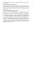
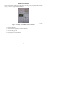
INSTALLATION Carton contains the following components. See Fig. 2 for programmable models or Fig. 3 for non--programmable models. A07756 Fig. 2 -- T6--PAC / T6--PHP Carton Contents 1. 2. 3. 4.
A07757 Fig. 3 -- T6--NAC / T6--NHP Carton Contents 1. 2. 3. 4. Display Module Stand--off for Equipment Control Module Screws and pig tail Equipment Control Module AC/HP Control Location AC/HP Control should be mounted: S Approximately 5 ft (1.5m) from floor. S Close to or in a frequently used room, preferably on an inside partitioning wall. S On a section of wall without pipes or duct work.
AC/HP Control should NOT be mounted: S Close to a window, on an outside wall, or next to a door leading to the outside. S Exposed to direct light or heat from a lamp, sun, fireplace, or other temperature--radiating objects which could cause a false reading. S Close to or in direct airflow from supply registers and return--air registers. S In areas with poor air circulation, such as behind a door or in an alcove. Installer should determine whether control will be installed as single--piece or two--piece.
! CAUTION UNIT DAMAGE HAZARD Failure to follow this caution may result in equipment damage or improper operation. Improper wiring or installation may damage AC/HP Control. Check to make sure wiring is correct before proceeding with installation or turning on power. 1. Turn off all power to equipment. 2. If an existing thermostat is being replaced a. Remove existing thermostat from wall. b. Disconnect wires from existing thermostat, 1 at a time. c.
! CAUTION ENVIRONMENTAL HAZARD Failure to follow this caution may result in environmental damage. Mercury is a hazardous waste. Federal regulations require that Mercury be disposed of properly. Two-- Piece Installation The following steps should be followed for the installation of the two--piece configuration. NOTE: The 2--wire pigtail is not intended to support the weight of the User Interface. Do not hang the User Interface from the equipment Control Module screw terminals. 1.
A07225 Fig. 4 -- Press Tabs to Remove Backplate A07226 Fig.
2. Route wires through large hole in mounting base. Level mounting base against wall (for aesthetic value only—Display Module need not be leveled for proper operation) and mark wall through 2 mounting holes. See Fig. 6. A07165 Fig. 6 -- Backplate Mounting 3. Drill two 3/16--in. mounting holes in wall where marked. Thermostat may be mounted to a standard junction box, if desired. Hole pattern on thermostat mounting base matches junction box mounting holes. 4.
6. Match and connect equipment wires to proper terminals of each connector block being careful not to over tighten the screws. Correct polarity must be observed when connecting the two wires from the Equipment Control Module to the thermostat mounting base. If wires are connected incorrectly, the Display Module will not operate. See Fig. 7, 8 and 9.
A07166 Fig. 8 -- Secure Wires to Terminal Strip A07167 Fig.
NOTE: The 2--wire pigtail is not intended to support the weight of the User Interface. Do not hang the User Interface from the equipment Control Module screw terminals. S Red is V+ S Black is Vg 7. Push any excess wire into wall and against mounting base. Seal hole in wall to prevent air leaks. Leaks can affect operation and cause incorrect temperature and/or humidity measurement. 8. Make sure to attach 2--wire pigtail to Display Module mounting base. It is packed loose in the box from the factory.
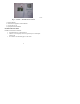
10. Find suitable indoor mounting location for Equipment Control Module, either near or on equipment. See Fig. 11. IMPORTANT NOTE: Equipment Control Module should not be mounted to duct work or below any other controls or equipment (i.e. humidistat, humidifier, etc.). A07217 Fig. 11 -- Equipment Control Module on Equipment 11. Route wires through rear of Equipment Control Module using either a clearance hole or supplied standoff. See Fig. 12.
A07227 Fig. 12 -- Standoff 12. Match and connect equipment wires to proper terminals of each connector block being careful not to over tighten the screws. Correct polarity must be observed when connecting the two wires from the Equipment Control Module to the thermostat mounting base. If wires are connected incorrectly, the Display Module will not operate. See Fig. 7, 8 and 9. 13. Snap cover over top of Equipment Control Module. See Fig. 13.
A07218 Fig. 13 -- Cover on Equipment Control Module 14. Turn on power to equipment. On power up, all display segments will light for 5 sec. For the next 5 sec a 2--digit code appears on large display which identifies AC/HP Control configuration. Refer to Option 33. a. AC — 1--stage air conditioner, AC, HP b. HP — 1--stage heat pump, HP only c. H — heating only system, AC, HP d.
wall (for aesthetic value only -- Equipment Control Module need not be leveled for proper operation) and mark wall through 2 mounting holes. 2. Drill two 3/16--in. mounting holes in wall where marked. Thermostat may be mounted to a standard junction box if desired. Hole pattern on Equipment Control Module matches junction box mounting holes. 3. Secure rear plastic Equipment Control Module to wall with 2 screws and anchors provided. Additional mounting holes are available for more secure mounting if needed.
5. Match and connect equipment wires to proper terminals of each connector block. 6. Push any excess wire into wall and against Equipment Control Module. Seal hole in wall to prevent air leaks. Leaks can affect operation and cause incorrect temperature and/or humidity measurement. 7. Remove 2--wire pigtail from thermostat mounting base and attach to Equipment Control Module terminal block (terminals V+ and Vg). Attach two--wire pigtail to the back of the Display Module via 2 pin, keyed connector. 8.
9. Turn on power to equipment. On power up, all display segments will light for 5 sec. For the next 5 sec a 2--digit code appears on large display which identifies AC/HP Control configuration. Refer to Option 33. a. AC — 1--stage air conditioner, AC, HP b. HP — 1--stage heat pump, HP only c. H — heating only system, AC, HP d. C — cooling only system, AC, HP Set AC/HP Control Configuration Configuration options enable the installer to configure the thermostat for a particular installation.
Option 07 — Zoning Option 08 — Auxiliary Heat Lockout Temperature Setting (only available when heat pump is used and when outdoor air temperature sensor is present) Option 10 — Reversing Valve Option 11 — Adjustable Setpoint Deadband Option 12 — Smart Recovery (programmable models only) Option 13 — Room Temperature Offset Adjustment Option 15 — Enable Auto Mode Option 16 — Cycles Per Hour Option 17 — Time Between Stages Option 18* — Backlight Configuration Option 19 — Dry Contact (programmable models only)
Option 31* — Daylight Savings Time Configuration (programmable models only) Option 32 — Furnace Heat Staging Option 33 — Single or Two--Piece Installation Option 99 — Reset to Factory Defaults TO ENTER CONFIGURATION MODE Press and hold FAN button for approximately 10 sec. The Display Module is now in configuration mode. It will automatically exit this mode if no button is pressed for 3 minutes. Pressing either FAN or DONE button will exit configuration mode immediately.
AC model — Range: AC, H, C. HP — operates a single--speed heat pump with a fan coil. AC — operates a single--speed AC. H — operates a heat--only system. Furnace or fan coil only; no outdoor unit. C — operates a cool only--system. Outdoor AC unit with an indoor fan coil with no strip heaters. Defaults HP model defaults to HP. AC model defaults to AC. Option 02 — Clean Filter Timer Select hours of blower operation (heating, cooling, or fan) before CHECK FILTER icon is displayed.
select OFF. Some auxiliary heaters require separate G signal to turn on blower. In this case, select On. Default is OF (off). Option 05 — Room Air Temperature Sensing (programmable models only) This selection determines which sensor the control will use for measuring room air temperature. Room air temperature can be sensed in one of three ways; the local sensor (L) located on the Display Module, the remote room air sensor (r), or the average of local and remote sensors (Lr). Settings are L, r, Lr.
OF (off) -- function is disabled. Auxiliary heat is allowed to operate whenever sufficient demand for heat is available. 5--55_F -- Outdoor temperature above which the auxiliary heat is not allowed to operate (unless MODE is set to Emergency Heat). Default is OF (off). Option 10 — Reversing Valve This selection is only available on heat pump systems. “O” terminal can be configured to be energized in either heating mode or in cooling mode, depending on heat pump operation.
programmed. Not available with non--programmable thermostats or when thermostat is configured as non--programmable. Default is 90. Option 13 — Room Air Temperature Offset Adjust The number of _F to be added to the displayed temperature to calibrate or deliberately miscalibrate the measured room temperature ( --5 to +5_F). Default is 0. Option 15 — Enable Auto Mode This selection is not available if the thermostat is configured as Heat Only or Cool Only in Option 1.
6 — The heating and cooling outputs will be energized no more than 6 times per hour. When an output is energized, it will not be energized again for 10 minutes. Default is 4. Option 17 — Time Between Equipment Stages This selection is only available for heat pump systems. This determines the minimum number of minutes of equipment operation on the highest compressor stage before allowing the transition to auxiliary heat. Available selections are 10, 15, 20, and 25.
value between 0 and 60 will be shown in the minutes display. See Operational Information and Wiring Diagrams for further explanation of dry contact configuration and use. To change the period or minutes, press the soft key below the period or minutes and then use the UP/DOWN buttons to change to the desired value. Default is OF (off). Option 20 — Outdoor Air Temperature Offset Adjustment This selection allows the calibration, or deliberate miscalibration of the outdoor air temperature sensor reading.
Option 21 — Keypad Lockout (non--programmable models only) This selection allows the installer to limit access to the keypad. Selections are OF (off), 1, 2. OF (off) — The user has full access to the keypad. 1 — The user has access to change the setpoints. 2 — The entire keypad is locked. When a button is pressed, the backlight will turn on but none of the operating parameters will be changed. When the keypad lock selection is turned on, the padlock icon will be displayed.
4 — Periods WAKE, DAY, EVE, and SLEEP are available. Default is 4. Option 26 — Minimum Cooling Setpoint This selection allows the installer to configure the minimum cooling setpoint that the user is allowed to set. The range is based on the value of the adjustable deadband Option 11, such that the minimum of the range is 50_F plus the adjustable deadband and the maximum is 90_F. Default is 52_F (based on the adjustable deadband default = 2).
OF (off) — The Humidifier Pad Reminder is disabled and will never be displayed. 1--24 — The number of months after which the Humidifier Pad Reminder icon will be displayed, “CHECK HUM PAD”. Default is OF (off). Option 30 — Programmable Fan (programmable models only) This selection allows the homeowner to program the fan selection to “Auto” or “On” fan operation for each of the program schedule periods. This selection is only available on programmable models.
Daylight Savings Time by setting the day of the week by selecting the appropriate triangle icon next to the days of the week, the month of the year will be set in the clock hours location (range 1--12) and the week of the month will be set in the clock minutes location. The week of the month selections will be F, 2, 3, 4, and L for First, 2nd, 3rd, 4th, and Last. So for the first Sunday in April, the display would show SUN, 4, F.
Option 99 — Reset to Factory Defaults Use this capability to reset the stat to “out of the box” conditions. BEWARE! All configuration settings, program settings, clock, and calendar which have been manually entered will be lost! When this option is selected, the configuration number (99), will appear on the left and 10 will appear on the right. To perform the reset, first use the MODE key to move the box from the 99 to the 10 (programmable model) or to flash the 10 (non--programmable model).
SYSTEM START--UP AND CHECKOUT The AC/HP Control is designed with a built--in installer test capability. It allows easy operation of equipment without delays or setpoint adjustments to force heating or cooling. To enable installer test mode, press and hold the fan button for 15 seconds. After 10 seconds, the thermostat will enter Configuration Mode. Continuing to hold the Fan button through 15 seconds will cause the thermostat to enter Installer Test Mode.
TO TEST FAN Fan button switches FAN icon between AUTO and On. While On is displayed, G output will be energized, turning fan on. Allow up to 10 sec after button is pressed for fan to turn on and off. On some fan coils, fan continues to operate for 90 sec after G signal is removed. Final Settings Be sure to press DONE to exit installer setup mode.
If fixed temperatures are desired, use SCHEDULE button to turn on arrow icon next to HOLD. This will maintain setpoints, not allowing them to change with programmed schedule. The FAN button may be used to select between AUTO (fan on only with equipment) and On (fan on continuously) fan modes. For further information on temperature selection and programming, refer to Homeowner’s Guide.
Vacation (programmable models only) A vacation selection is available specifically for times where the home will not be occupied for an extended period. Vacation mode has an automatic hold, meaning that setpoints are not affected by the programmed schedule. Vacation mode is active for a specified period of time. While in vacation mode, the system provides temperature protection for the home in the selected mode, but not comfort.
Cycle Timer Based on the selection of 2, 4, or 6 cycles per hour, this timer is set to 30, 15, or 10 minutes. This much time must elapse from the start of one cycle before another cycle can start. It serves to impose the cycles per hour limits. It can be defeated for one cycle by simultaneously pressing the FAN and UP buttons. Ten--Minute Staging Timer In multistage heating or cooling, this timer prevents any higher stage from turning on until preceding stage has been on for 10 minutes.
Three--Minute Minimum on Time In normal operation, when a stage turns on, it will not turn off for a minimum of 3 minutes. If the setpoint is changed, this timer is canceled, allowing the equipment to turn off immediately when the demand is removed. Heat/Cool Setpoints (Desired Temperature) A minimum difference of 1_F and maximum of 6_F is enforced between heating and cooling desired temperatures. This is done by allowing 1 setting to “push” the other, to maintain this difference.
Programmable Fan (programmable models only) The fan output can be programmed based on period of the day. When programming for each day and period the fan can be set to On or AUTO. Dry Contact On the programmable models, the dry contact that can be used for control of an auxiliary device. The dry contact may be configured to be closed for a specific number of minutes per hour for each period of the program schedule. This can be used to operate a ventilator, damper, system blower, or other auxiliary device.
TROUBLESHOOTING If the display module doesn’t power up after power is applied, check the Rc/Rh and C terminals for 24VAC. If 24VAC is present, check the voltage between Vg and V+. This voltage will be approximately 12--20VDC. If voltage is present, check the polarity to make sure it is wired correctly. The display will not power up if polarity is reversed.
Table 3 – Equipment Configuration Outputs HEAT STAGE 2 HEAT STAGE 3 EM HEAT STAGE 1 W/W1 - - - W/W1 W/W1 O/W2/B - - - Y/Y2 Y/Y2 W/W1 - W/W1 Y/Y2 - Y/Y2 O/W2/B Y/Y2 W/W1 O/W2/B - W/W1 AC HP - - W/W1 - - - AC HP Y/Y2 - - - - - EQUIPMENTCONFIGURATION OPTION #1 HARDWARE CONFIGURATION COOL STAGE 1 COOL STAGE 2 HEAT STAGE 1 Single-- stage AC AC Y/Y2 - Single-- stage AC HP Y/Y2 - Single-- stage HP RVS = C HP Y/Y2 O/W2/B Single-- stage HP RVS = H HP Heat Only Un
WIRING DIAGRAMS Display module Display module wall mount Equipment Control Module V+ Fan Coil Heat Pump V+ O O V+ Vg V+ RVS/Heat Stage 2 Vg O/B W2 W3 W2 Vg Vg Heat Stage 1 W/W1 W2 Compressor Y/Y2 Y Not Used Y1 Y Fan G G 24VAC Hot Heating Rh R R 24VAC Hot Cooling Rc Dry Contact 1 D1 Dry Contact 2 D2 24VAC Common C COM COM Outdoor Air Temp OAT Remote Room Sensor RRS Outdoor Sensor * OAT/RRS Com OAT/RRS Remote Room Sensor * A07164 Fig.
Thermostat Fan Coil Heat Pump O O RVS/Heat Stage 2 O/B W2 W3 W2 Heat Stage 1 W/W1 W2 Compressor Y/Y2 Y Not Used Y1 Y Fan G G 24VAC Hot Heating Rh R R 24VAC Hot Cooling Rc Dry Contact 1 D1 Dry Contact 2 D2 24VAC Common C COM COM Outdoor Air Temp OAT Remote Room Sensor RRS Outdoor Sensor * OAT/RRS Com OAT/RRS Remote Room Sensor * A007081 Fig. 17 -- Fan Coil with Heat Pump (HP Thermostat) * Indicates connection may not be required/available.
Thermostat Fan Coil O RVS/Heat Stage 2 O/B W2 W3 Heat Stage 1 W/W1 W2 Compressor Y/Y2 Not Used Y1 Fan G G 24VAC Hot Heating Rh R 24VAC Hot Cooling Rc Dry Contact 1 D1 Dry Contact 2 D2 24VAC Common C Humidify HUM Outdoor Air Temp OAT Humidifier Solenoid Valve * Remote Room Sensor RRS Outdoor Sensor * OAT/RRS Com OAT/RRS Remote Room Sensor * Aux. Connection COM A07082 Fig.
Thermostat Fan Coil Air Conditioner O RVS/Heat Stage 2 O/B W2 W3 Heat Stage 1 W/W1 W2 Compressor Y/Y2 Y Not Used Y1 Y Fan G G 24VAC Hot Heating Rh R R 24VAC Hot Cooling Rc Dry Contact 1 D1 Dry Contact 2 D2 24VAC Common C COM COM Outdoor Air Temp OAT Remote Room Sensor RRS Outdoor Sensor * OAT/RRS Com OAT/RRS Remote Room Sensor * A07083 Fig. 19 -- Fan Coil with Air Conditioner (AC Thermostat) * Indicates connection may not be required/available.
Thermostat Fan Coil O RVS/Heat Stage 2 O/B W2 W3 Heat Stage 1 W/W1 W2 Compressor Y/Y2 Not Used Y1 Fan G G 24VAC Hot Heating Rh R 24VAC Hot Cooling Rc Dry Contact 1 D1 Dry Contact 2 D2 24VAC Common C Humidify HUM Outdoor Air Temp OAT Humidifier Solenoid Valve * Remote Room Sensor RRS Outdoor Sensor * OAT/RRS Com OAT/RRS Remote Room Sensor * Aux. Connection COM A07084 Fig.
Thermostat Furnace Heat Stage 1 W/W1 W Compressor Y/Y2 Y Not Used Y1 Air Conditioner Y Fan G G 24VAC Hot Heating Rh R R 24VAC Hot Cooling Rc Dry Contact 1 D1 Dry Contact 2 D2 24VAC Common C COM COM Outdoor Air Temp OAT Remote Room Sensor RRS Outdoor Sensor * OAT/RRS Com OAT/RRS Remote Room Sensor * A07085 Fig. 21 -- Furnace with Air Conditioner (AC Thermostat) * Indicates connection may not be required/available.
Thermostat RVS/Heat Stage 2 O/B W2 Heat Stage 1 W/W1 Compressor Y/Y2 Not Used Y1 Fan G G 24VAC Hot Heating Rh R 24VAC Hot Cooling Rc Dry Contact 1 D1 Dry Contact 2 D2 24VAC Common C Humidify HUM Outdoor Air Temp OAT Remote Room Sensor RRS OAT/RRS Com OAT/RRS C A07086 Fig. 22 -- Thermostat with Dry Contact Control for Run Time * Indicates connection may not be required/available.
Thermostat Furnace Air Conditioner W2 RVS/Heat Stage 2 O/B W2 Heat Stage 1 W/W1 W1 Compressor Y/Y2 Y Not Used Y1 Y Fan G G 24VAC Hot Heating Rh R R 24VAC Hot Cooling Rc Dry Contact 1 D1 Dry Contact 2 D2 24VAC Common C COM COM Outdoor Air Temp OAT Remote Room Sensor RRS Outdoor Sensor * OAT/RRS Com OAT/RRS Remote Room Sensor * A07089 Fig. 23 -- 2--Stage Furnace with Air Conditioner (HP Thermostat Configured as AC) * Indicates connection may not be required/available.
Single-Stage Furnace Thermostat RVS/Heat Stage 2 O/B W2 Heat Stage 1 W/W1 Compressor Low Y1 Compressor High Y/Y2 Y Fan G G 24VAC Hot Heating Rh R 24VAC Hot Cooling Rc Dry Contact 1 D1 Dry Contact 2 D2 24VAC Common C Humidify HUM Single-Stage Air Conditioner W Y R COM Outdoor Air Temp OAT Humidifier Solenoid Valve * Remote Room Sensor RRS Outdoor Sensor * OAT/RRS Com OAT/RRS Remote Room Sensor * * COM A07170 Fig.
THERMOSTAT CONFIGURATION RECORD Installer _________________________ Model Number ______________________________ Date _________________________ A. Hardware Configuration __________ Seal Hole In Wall B. Mode Settings __________ Mode (Off, Heat, Cool, Auto, Em Heat) __________ Heating Setpoint Value __________ Cooling Setpoint Value __________ Fan (Auto or On) C. Home, Away, Sleep Settings Home Away Sleep Heat Cool ____ ____ ____ ____ ____ ____ D.
E Configuration Options Option 01 Option 02 Option 03* Option 04 Option 05 Option 06 Option 07 Option 08 Option 10 Option 11 Option 12 Option 13 Option 15 Option 16 Option 17 Option 18* Option 19 Option 20 _____ _____ _____ _____ _____ _____ _____ _____ _____ _____ _____ _____ _____ _____ _____ _____ _____ _____ Equipment Type Clean Filter Timer Adjustment Fahrenheit/Centigrade Selection Fan (G) on with W/W1 Selection Room Air Temperature Sensing Cooling Lockout Below 55_F Selection (only available if out
E Configuration Options (cont) Option 21* Option 24* Option 25* Option 26 Option 27 Option 28 Option 29 Option 30* Option 31* Option 32 Option 33 _____ _____ _____ _____ _____ _____ _____ _____ _____ _____ _____ Keypad Lockout Programmable/Non-- Programmable (programmable models only) Number of Programmable Periods Per Day (programmable models only) Minimum Cooling Setpoint Maximum Heating Setpoint UV Light Reminder Humidifier Pad Reminder Programmable Fan (programmable models only) Daylight Savings Time