GT-X 50YBV Ultra High Efficiency Vertical Two-Stage Geothermal System INSTALLED BY: Installation, Operation & Maintenance Instructions Revision: 07/21/05D TABLE OF CONTENTS Model Nomenclature 2 Electrical Data 13 Storage 2 Blower Speed Selection 14 Physical Data 3 Blower Performance Table 16 Pre-Installation 3 Electrical - Low Voltage 16 Physical Dimensions 4 Freeze Protection Selection 16 Unit Installation 5 Water Valve Wiring 17 Duct System 5 Electrical Wiring Schematic 17 W
GENERAL INFORMATION Model Nomenclature 1 2 3 4 5 6 7 8 9 10 11 12 5 0 Y B V 0 3 6 L L A 3 5 1 SERIES: SIZE: YBV = VERTICAL UPFLOW TWIN 036 042 048 060 072 PACKAGING: 1 = SINGLE PACK (DOMESTIC) REVISION LEVEL: 5 = CURRENT REVISION AIR FLOW CONFIGURATION: OPTION RETURN L R LEFT RIGHT DISCHARGE FILTER TOP TOP 1.000" 1.
Pre-Installation Installation, operation and maintenance instructions are provided with each unit. Before unit start-up, read all manuals and become familiar with the unit and its operation. Thoroughly check the system before operation. To avoid equipment damage, DO NOT use these units as a source of heating or cooling during the construction process. The mechanical components and filters used in these units will quickly become clogged with construction dirt and debris which may cause system damage.
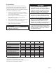
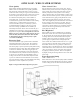
INSTALLATION Physical Dimensions Legend 1 2 3 4 5 6 7 8 9 10 Water Inlet for Circuit A - 1" FPT Swivel Connection Water Inlet for Circuit B - 1" FPT Swivel Connection Water Outlet for Circuit A - 1" FPT Swivel Connection Water Outlet for Circuit B - 1" FPT Swivel Connection Condensate - 3/4" FPT Connection Hot Water Generator Inlet for Circuit A - 1/2" FPT Hot Water Generator Outlet for Circuit A - 1/2" FPT Low voltage thermostat knockout for 1/2" conduit External Pump Power lmockout for 1/2" conduit Unit
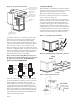
INSTALLATION The installation of geothermal heat pump units and all associated components, parts and accessories which make up the installation shall be in accordance with the regulations of ALL authorities having jurisdiction and MUST conform to all applicable codes. It is the responsibility of the Installing Contractor to determine and comply with ALL applicable codes and regulations. Figure 1a.
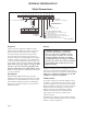
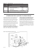
Figure 1b. Typical Ductwork Detail Condensate Drain Internally insulate supply duct for first 4’ [1.2m] each way to reduce noise Use turning vanes in supply transition Flexible canvas duct connector to reduce noise and vibration Rounded return transition Rev 3/27/00 Internally insulate return transition duct to reduce noise Each unit utilizes a condensate hose inside the cabinet as a trapping loop, therefore an external trap is not necessary. Figure 5 shows typical condensate connections.
GROUND LOOP APPLICATION Piping Installation Flushing the Earth Loop The typical closed loop ground source system is shown in Figure 10. All earth loop piping materials should be limited to only polyethylene fusion in inground sections of the loop and galvanized or steel fitting should not be used at any time due to their tendency to corrode. All plastic to metal threaded fittings should be avoided as well due to their potential to leak in earth coupled applications and a flanged fitting substituted.
Antifreeze may be added before, during or after the flushing procedure. However, depending upon which time is chosen, antifreeze could be wasted when emptying the flush cart tank. See antifreeze section for more details. Loop static pressure will fluctuate with the seasons. Pressures will be higher in the winter months than during the cooling season. This fluctuation is normal and should be considered when charging the system initially.
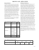
OPEN LOOP - WELL WATER SYSTEMS Water Quality Water Control Valve Water quality should be plentiful and of good quality. Table 4 shows recommended water quality guidelines. The unit can be ordered with either a copper or cupronickel water heat exchanger. Copper is recommended for closed loop systems and open loop ground water systems that are not high in mineral content or corrosiveness. In conditions anticipating heavy scale formation or in brackish water, a cupro-nickel heat exchanger is recommended.
Table 4. Water Quality Standards Acidity pH Total Hardness Iron Oxides Iron Bacteria Corrosiveness Brackish 7 to 9 range for copper. Cupro-nickel may be used in the 5-9 range. Calcium and magnesium carbonate should not exceed 20 grains per gallon (350 ppm) Less than 1 ppm No level allowable Max Allowable Level Coax Mtl Ammonia, Ammonium hydroxide 0.5 ppm Cu Ammonium chloride, Ammonium nitrate 0.5 ppm Cu Ammonium Sulfate 0.5 ppm Cu Chlorine/Chlorides 0.
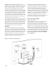
HOT WATER GENERATOR The HWG (Hot Water Generator) or desuperheater option provides considerable operating cost savings by utilizing excess heat energy from the heat pump to help satisfy domestic hot water requirements. The HWG is active throughout the year, providing virtually free hot water when the heat pump operates in the cooling mode or hot water at the COP of the heat pump during operation in the heating mode.
lower elements and thermostats, the lower element should be turned down to 100°F or lowest setting, while the upper element should be adjusted to 120°F. Depending upon the specific needs of the customer, you may want to adjust the upper element differently. On tanks with a single thermostat, lower the thermostat setting to 120°F or the “LOW” position. Figure 15.
ELECTRICAL-LINE VOLTAGE All field installed wiring, including electrical ground, must comply with the National Electrical Code as well as all applicable local codes. WARNING To avoid possible injury or death due to electrical shock, open the power supply disconnect switch and secure it in an open position during installation. Refer to the unit wiring diagrams for fuse sizes and a schematic of the field connections which must be made by the installing (or electrical) contractor.
ECM FAN MOTOR The ECM fan is controlled by an interface board that converts thermostat inputs and field selectable CFM settings to signals used by the ECM motor controller. Units manufactured before July 2005 have version I (P/N 69243707). Units manufactured after July 2005 have version II (P/N 17B0019N01). Fan speeds are selected with jumpers for version I or via a nine position DIP switch for version II.
ECM FAN MOTOR Table 6: ECM Board Tap Settings Cooling settings: 50YB,YC,YD,YE units* Version II Version I 17B0019N01 69243707 DIP Switch Tap HP CFM Setting Jumper SW1 SW2 1 1 ON ON 2 2 ON OFF 3 3 OFF ON 4 4 OFF OFF *50YB & YC units use the same settings for both cooling (normal) CFM and heating CFM. Heating settings: 50YD, YE units* Version II Version I 17B0019N01 69243707 DIP Switch Tap DELAY Setting Jumper SW3 SW4 1 1 ON ON 2 2 ON OFF 3 3 OFF ON 4 4 OFF OFF *This table not used for 50YB, YC units.
ECM FAN MOTOR Table 6. Blower performance table and fan speed selection Model Max ESP (in wg) Normal Mode Fan Motor (hp) 036 0.5 1/2 042 0.5 1/2 048 0.
Accessory Connections Thermostat Selection and Wiring A terminal paralleling the compressor contactor coil have been provided on the CXM/DXM control of the GT-X line. "A" has been provided to control accessory devices, such as water valves, electronic air cleaners, humidifiers, etc. Note: This terminal should be used only with 24 volt signals and not line voltage signals. This signal operates with the compressor contactor. See Figure 21 or the wiring schematic for details.
Electrical Schematic Page 18
CXM Control Description Retry Mode - If the control is attempting a retry of a fault, the status LED will slow flash (slow flash = one flash every 2 seconds) to indicate the control is in process of retrying. Features • Anti-short cycle protection • High and Low pressure cutouts NOTE: In the following field configuration options, jumper wires should be clipped ONLY when power is removed from the CXM control.
Safety Features The following safety features are provided to protect the compressor, heat exchangers, wiring and other components from damage caused by operation outside of design conditions. Anti-Short Cycle Protection- The control features a 5 minute anti-short cycle protection for the compressor. Note: The 5 minute anti-short cycle also occurs at power up. Random Start - The control features a random start upon power up of from 5-80 seconds.
Diagnostic Features The Status LED on the CXM control advises the serviceman of the current status of the CXM control. The status LED can display either the current CXM mode or the last fault memory if in test mode. See Table 7 for a complete listing of codes. Unit Operation Description PowerUp - The unit will not operate until all the inputs and safety controls are checked for normal conditions. Note: The compressor will have a 5 minute anti-short cycle delay at power-up.
Troubleshooting Information General CXM board troubleshooting in general is best summarized as simply varifying inputs and outputs. After this process has been varified, confidence in board operation is confirmed and the trouble must be else where. Below are some general guidelines required for developing training materials and procedures when applying the CXM control. The thermistor resistance should be measured with the connector removed so that only the impedance of the thermistor is measured.
TROUBLE ANALYSIS After completing the preliminary checks described above, be sure to inspect for other obvious problems such as leaking connections, broken or disconnected wires, etc. Preliminary Trouble Inspection WARNING If everything appears to be in order, but the unit still fails to operate properly, refer to the following Troubleshooting Chart. HAZARDOUS VOLTAGE! DISCONNECT ALL ELECTRIC POWER INCLUDING REMOTE DISCONNECTS BEFORE SERVICING.
Functional Troubleshooting Fault Main power Problems Htg Clg Possible Cause X HP Fault-Code 2 High pressure Solution X Green Status LED Off X Reduced or no water flow in cooling X Water Temperature out of range in Bring water temp within design parameters cooling X Reduced or no Air flow in heating Check Line Voltage circuit breaker and disconnect Check for line voltage between L1 and L2 on the contactor Check for 24VAC between R and C on CXM/DXM Check primary/secondary voltage on transformer Ch
Functional Troubleshooting (cont.) Only Compressor Runs X X Thermostat wiring Check G wiring at heat pump. Jumper G and R for fan operation. X X Fan motor relay Jumper G and R for fan operation. Check for Line voltage across BR contacts. X X Fan motor Check for line voltage at motor.
UNIT START UP Operating Limits Environment – This unit is designed for indoor installation ONLY. Power Supply – A voltage variation of +/– 10% of nameplate utilization voltage is acceptable. Starting Conditions Determination of operating limits is dependent primarily upon three factors: 1) return air temperature 2) water temperature and 3) ambient temperature. When any one of these factors is at minimum or maximum levels, the other two factors should be at normal levels to ensure proper unit operation.
e. Refer to Table 11. Check the difference in temperature of supply and return water temperature, usually referred to as Delta-T Water. If Delta-T Water is outside the range shown in table 11, check cooling refrigerant pressure in table 13. Verify correct water flow by comparing unit pressure drop across the heat exchanger versus the data in Table 12. Heat of rejection can be calculated and compared to the specification catalog.
Table 11. Water Temperature Change Through Heat Exchanger Water Circuits Headered Together For Closed Loop: Ground Source or Delta-T Rise (Clg) 4.
Page 29
Page 30
Page 31 Please refer to the Carrier Installation, Operation and Maintenance Manual for operating and maintenance instructions. Rev.: 6/03 Part No.: CA185 NOTE: Some states or Canadian provinces do not allow limitations on how long an implied warranty lasts, or the limitation or exclusions of consequential or incidental damages, so the foregoing exclusions and limitations may not apply to you.
PREVENTIVE MAINTENANCE Water Coil Maintenance – (Direct Ground Water Applications Only) If the installation is performed in an area with a known high mineral content (125 P.P.M. or greater) in the water, it is best to establish with the owner a periodic maintenance schedule so the coil can be checked regularly. Consult the well water applications section of this manual for a more detailed water coil material selection.