Horizontal & Vertical Packaged Products GT-PX (50YD) Two-Stage Puron® Series GT-PG (50YE) Single-Stage Puron® Series GT-G (50YC) Packaged R22 Series Residential Horizontal & Vertical Packaged Geothermal Heat Pumps Installation, Operation & Maintenance Instructions 97B0046N01 Revision: 21 Aug, 2007D Table of Contents Model Nomenclature 2 Low Water Temperature Cutout Selection 31 Storage 3 Water Valve Wiring 32 Pre-Installation 3 Thermostat Wiring 33-34 Physical Data 4-5 ECM Blower Control 35
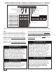
MODEL NOMENCLATURE: GENERAL OVERVIEW FOR ALL H & V SERIES 1 2 3 4 5 6 7 8 9 10 11 12 5 0 Y E V 0 2 4 L C A 3 0 1 UNIT TYPE: SIZE: YE = GT-PG SINGLE-STAGE PURON® REFRIG YD = GT-PX TWO-STAGE PURON® REFRIG YC = GT-G SINGLE-STAGE R22 REFRIG 018 024 030 036 042 048 060 072 CONFIGURATION: V = VERTICAL UPFLOW H = HORIZONTAL D = VERTICAL DOWNFLOW AIR FLOW CONFIGURATION - ECM: RETURN J K LEFT RIGHT DISCHARGE MOTOR TOP TOP ECM ECM RETURN J K LEFT RIGHT DISCHARGE MOTOR DOWN DOWN ECM ECM REVI
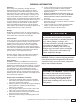
GENERAL INFORMATION Inspection Upon receipt of the equipment, carefully check the shipment against the bill of lading. Make sure all units have been received. Inspect the packaging of each unit, and inspect each unit for damage. Insure that the carrier makes proper notation of any shortages or damage on all copies of the freight bill and completes a common carrier inspection report. Concealed damage not discovered during unloading must be reported to the carrier within 15 days of receipt of shipment.
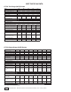
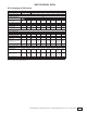
UNIT PHYSICAL DATA GT-PX Two-Stage (50YD) Series Model 026 038 Compressor (1 Each) 049 064 072 Copeland UltraTech Two-Stage Scroll Factory Charge R410a, oz [kg] 58 [1.64] 78 [2.21] 81 [2.30] 144 [4.08] 156 [4.
UNIT PHYSICAL DATA GT-G Packaged (GT-G) Series Model 015 Compressor (1 Each) Factory Charge R22, oz [kg] 018 024 030 036 Rotary 042 048 060 070 74 [2.0] 74 [2.10] 102 [2.89] 104 [2.95] Copeland Scroll 44 [1.25] 44 [1.25] 48 [1.36] 48 [1.36] 60 [1.
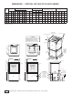
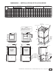
DIMENSIONS — VERTICAL UPFLOW GT-PX (50YD) SERIES Vertical A B C Width Depth Height 026 038 049 064 072 Water Connections Overall Cabinet Upflow Model 1 D 2 E In Out 3 F HWG In 4 5 G H HWG CondOut ensate in. 22.4 25.6 48.5 2.1 10.0 13.9 16.9 7.8 cm. 56.8 65.1 123.2 5.2 25.4 35.2 42.9 19.8 Electrical Knockouts Loop Water IPT J 1/2" cond Low Voltage HWG IPT 1" Swivel 1" Swivel in. 25.4 30.6 50.5 3.4 10.8 15.6 18.9 7.8 cm. 64.5 77.8 128.3 8.6 27.5 39.7 47.
DIMENSIONS — VERTICAL DOWNFLOW GT-PX (50YD) SERIES Vertical Downflow Model Water Connections Overall Cabinet A B C Width Depth Height 026 038 049 064 072 1 D 2 E In Out 3 F HWG In 4 5 G H HWG CondOut ensate in. 22.4 25.6 52.5 2.1 10.0 13.9 16.9 3.6 cm. 56.8 65.1 133.4 5.2 25.4 35.2 42.9 9.2 in. 25.4 30.6 54.5 3.4 10.8 15.6 18.9 3.6 cm. 64.5 77.8 138.4 8.6 27.5 39.7 47.9 9.2 in. 25.4 30.6 58.5 3.4 10.8 15.6 18.9 3.6 cm. 64.5 77.8 148.6 8.6 27.
DIMENSIONS — HORIZONTAL GT-PX (50YD) SERIES Water Connections Overall Cabinet Horizontal Model A B C Width Depth Height 026 038 049 064 072 1 D 2 E In Out 3 F HWG In 4 5 G H HWG CondOut ensate in. 22.4 62.2 19.3 2.1 10.0 13.9 16.9 0.6 cm. 56.8 158.0 48.9 5.2 25.4 35.2 42.9 1.5 in. 25.4 71.2 21.3 3.4 10.8 15.6 18.9 0.6 cm. 64.5 180.8 54.0 8.6 27.5 39.7 47.9 1.5 in. 25.4 76.2 21.3 3.4 10.8 15.6 18.9 0.6 cm. 64.5 193.5 54.0 8.6 27.5 39.7 47.9 1.
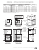
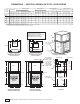
DIMENSIONS — VERTICAL UPFLOW GT-PG (50YE) SERIES Vertical in. 22.4 25.6 44.6 2.1 10.0 3 F HWG In 13.9 cm. 56.8 65.1 123.2 5.2 25.4 35.2 42.9 A B C Width Depth Height 018 024 030 036 Water Connections Overall Cabinet Upflow Model 1 D 2 E In Out 4 5 G H HWG CondOut ensate 16.9 7.8 19.8 in. 22.4 25.6 48.5 2.1 10.0 13.9 16.9 7.8 cm. 56.8 65.1 123.2 5.2 25.4 35.2 42.9 19.8 in. 25.4 30.6 50.5 3.4 10.8 15.6 18.9 7.8 cm. 64.5 77.8 128.3 8.6 27.5 39.7 47.
DIMENSIONS — VERTICAL DOWNFLOW GT-PX (50YD) SERIES Vertical in. 22.4 25.6 48.6 2.1 10.0 3 F HWG In 13.9 cm. 56.8 65.1 123.4 5.2 25.4 35.2 A B C Width Depth Height 018 024 030 036 Water Connections Overall Cabinet Downflow Model 1 D 2 E In Out 4 5 G H HWG CondOut ensate 16.9 3.6 42.9 9.2 in. 22.4 25.6 52.5 2.1 10.0 13.9 16.9 3.6 cm. 56.8 65.1 133.4 5.2 25.4 35.2 42.9 9.2 in. 25.4 30.6 54.5 3.4 10.8 15.6 18.9 3.6 cm. 64.5 77.8 138.4 8.6 27.5 39.
DIMENSIONS — HORIZONTAL GT-PG (50YE) SERIES Water Connections Overall Cabinet Horizontal Model A B C Width Depth Height 018 024 030 036 1 D 2 E In Out 3 F HWG In 4 5 G H HWG CondOut ensate in. 22.4 62.2 19.3 2.1 10.0 13.9 16.9 0.6 cm. in. 56.8 22.4 158.0 62.2 48.9 19.3 5.2 2.1 25.4 10.0 35.2 13.9 42.9 16.9 1.5 0.6 cm. 56.8 158.0 48.9 5.2 25.4 35.2 42.9 1.5 in. 25.4 71.2 21.3 3.4 10.8 15.6 18.9 0.6 cm. 64.5 180.8 54.0 8.6 27.5 39.7 47.9 1.
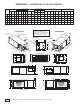
DIMENSIONS — VERTICAL UPFLOW GT-G (50YC) SERIES Overall Cabinet Upflow Model A B C Width Depth Height 015-018 024-030 036 042-048 060 070 in. cm. in. cm. in. cm. in. cm. in. cm. in. cm. 22.4 56.8 22.4 56.8 22.4 56.8 25.4 64.5 25.4 64.5 25.4 64.5 25.6 65.1 25.6 65.1 25.6 65.1 30.6 77.8 30.6 77.8 30.6 77.8 40.4 102.6 44.4 112.8 48.4 122.9 50.4 128.0 54.4 138.2 58.4 148.3 1 D In 2.4 6.1 2.4 6.1 2.4 6.1 2.4 6.1 2.4 6.1 2.4 6.
DIMENSIONS — VERTICAL DOWNFLOW GT-G (50YC) SERIES Overall Cabinet Downflow Model A B 1 D C Width Depth Height 015-018 024-030 036 042-048 060 070 in. cm. in. cm. in. cm. in. cm. in. cm. in. cm. 22.4 56.8 22.4 56.8 22.4 56.8 25.4 64.5 25.4 64.5 25.4 64.5 25.6 65.1 25.6 65.1 25.6 65.1 30.6 77.8 30.6 77.8 30.6 77.8 44.4 112.8 48.4 122.9 52.4 133.1 54.4 138.2 58.4 148.3 62.4 158.5 In 17 42.9 17 42.9 17 42.9 19 48.0 19 48.0 19 48.
DIMENSIONS — HORIZONTAL GT-G (50YC) SERIES Overall Cabinet Horizontal 1 Model A B C Width Depth Height 015-018 024-030 036 042-048 060 070 22.4 22.4 22.4 25.4 25.4 25.4 53.0 63.0 63.0 72.0 77.0 82.0 19.3 19.3 19.3 21.3 21.3 21.3 Water Connections* 2 3 4 5 D E In Out 2.4 2.4 2.4 2.4 2.4 2.4 5.4 5.4 5.4 5.4 5.4 5.4 Electrical Knockouts F G H J K L HWG HWG CondLow Ext Power In Out ensate Voltage Pump Supply Discharge Connection 13.9 13.9 13.9 15.9 15.9 15.9 16.9 16.9 16.9 18.9 18.9 18.
HORIZONTAL INSTALLATION NOTICE! Failure to remove shipping brackets from spring-mounted compressors will cause excessive noise, and could cause component failure due to added vibration. Horizontal Unit Location Units are not designed for outdoor installation. Locate the unit in an INDOOR area that allows enough space for service personnel to perform typical maintenance or repairs without removing unit from the ceiling. Horizontal units are typically installed above a false ceiling or in a ceiling plenum.
HORIZONTAL INSTALLATION Figure 3: Typical Horizontal Unit Installation 3/8" [10mm] threaded rods (by others) Return Air Thermostat Wiring Power Wiring Stainless steel braid hose with integral "J" swivel Optional Balancing Valve Supply Air Optional Low Pressure Drop Water Control Valve (can be internally mounted on some models) Unit Power Building Loop Insulated supply duct with at least one 90 deg elbow to reduce air noise Flexible Duct Connector Unit Power Disconnect (by others) Water Out Water I
FIELD CONVERSION OF AIR DISCHARGE Overview Horizontal units can be field converted between side (straight) and back (end) discharge using the instructions below. Figure 4: Left Return Side to Back Remove Screws Water Connection End Return Air Note: It is not possible to field convert return air between left or right return models due to the necessity of refrigeration copper piping changes. Preparation It is best to field convert the unit on the ground before hanging.
HORIZONTAL INSTALLATION Condensate Piping – Horizontal Units Pitch the unit toward the drain as shown in Figure 2 to improve the condensate drainage. On small units (less than 2.5 tons/8.8 kW), insure that unit pitch does not cause condensate leaks inside the cabinet. The horizontal run of a condensate hose is usually too short to cause drainage problems.
VERTICAL INSTALLATION Vertical Unit Location Units are not designed for outdoor installation. Locate the unit in an INDOOR area that allows enough space for service personnel to perform typical maintenance or repairs without removing unit from the mechanical room/closet. Vertical units are typically installed in a mechanical room or closet. Never install units in areas subject to freezing or where humidity levels could cause cabinet condensation (such as unconditioned spaces subject to 100% outside air).
VERTICAL INSTALLATION Sound Attenuation for Vertical Units Sound attenuation is achieved by enclosing the unit within a small mechanical room or a closet. Additional measures for sound control include the following: 1. Mount the unit so that the return air inlet is 90° to the return air grille. Refer to Figure 9. Install a sound baffle as illustrated to reduce line-of sight sound transmitted through return air grilles. 2.
WATER CONNECTION INSTALLATION External Flow Controller Mounting The Flow Controller can be mounted beside the unit as shown in Figure 12. Review the Flow Controller installation manual for more details. Water Connections-Residential (Distributor) Models Residential models utilize swivel piping fittings for water connections that are rated for 450 psi (3101 kPa) operating pressure.
GROUND-LOOP HEAT PUMP APPLICATIONS pressure is reached. Open the return valve and a pressure surge will be sent through the loop to help purge air pockets from the piping system. 4. Notice the drop in fluid level in the flush cart tank when the return valve is shut off. If air is adequately purged from the system, the level will drop only 1-2 inches (2.5 - 5 cm) in a 10” (25 cm) diameter PVC flush tank (about a half gallon [2.3 liters]), since liquids are incompressible.
GROUND-LOOP HEAT PUMP APPLICATIONS Figure 12: Typical Ground-Loop Application Flow Controller Unit Power Disconnect Insulated Hose Kit Thermostat Wiring P/T Plugs Rev.: 06/10/05D ASP30 Air Pad or Extruded polystyrene insulation board Do not install bricks or blocks under air pad. GROUND-WATER HEAT PUMP APPLICATIONS Open Loop - Ground Water Systems Typical open loop piping is shown in Figure 13. Shut off valves should be included for ease of servicing.
GROUND-WATER HEAT PUMP APPLICATIONS items. For example, an expansion tank that is too small can causing premature pump failure due to short cycling. Variable speed pumping applications should be considered for the inherent energy savings and smaller expansion tank requirements. Water Control Valve Note the placement of the water control valve in figure 13.
WATER QUALITY STANDARDS Table 3: Water Quality Standards Water Quality Parameter HX Material Closed Recirculating Open Loop and Recirculating Well Scaling Potential - Primary Measurement Above the given limits, scaling is likely to occur. Scaling indexes should be calculated using the limits below. pH/Calcium Hardness All Method - pH < 7.
HOT WATER GENERATOR The HWG (Hot Water Generator) or desuperheater option provides considerable operating cost savings by utilizing excess heat energy from the heat pump to help satisfy domestic hot water requirements. The HWG is active throughout the year, providing virtually free hot water when the heat pump operates in the cooling mode or hot water at the COP of the heat pump during operation in the heating mode.
HOT WATER GENERATOR Figure 16: Alternate HWG Piping with concentric/coaxial fitting (part #S69619804 not included with unit) Installation The HWG high limit temperature switch is set at 125°F [52°C] and is located on the HWG heat exchanger “Water In” line. If the HWG is connected incorrectly or if circulation is reversed, the aquastat will sense leaving water temperature and prevent HWG operation.
ELECTRICAL - LINE VOLTAGE ѥ WARNING! ѥ ѥ CAUTION! ѥ WARNING! To avoid possible injury or death due to electrical shock, open the power supply disconnect switch and secure it in an open position during installation. CAUTION! Use only copper conductors for field installed electrical wiring. Unit terminals are not designed to accept other types of conductors.
ELECTRICAL - LINE VOLTAGE Table 4c: GT-G Packaged (50YC) Series Electrical Data Compressor Model RLA LRA Qty HWG Pump FLA Ext Loop Pump FLA Fan Motor FLA Total Unit FLA Min Circuit Amps Max Fuse/ HACR Min AWG Max Ft (m) PSC Electrical Data 015 6.1 29.0 1 0.4 4.0 1.0 11.5 13.0 15 12 56 (17.2) 018 7.7 38.0 1 0.4 4.0 1.0 13.1 15.0 20 12 77 (23.6) 024 10.3 56.0 1 0.4 4.0 1.1 15.8 18.4 25 10 100 (30.7) 030 12.2 67.0 1 0.4 4.0 1.3 17.9 21.0 30 10 88 (26.
ELECTRICAL - POWER WIRING Power Connection Line voltage connection is made by connecting the incoming line voltage wires to the “L” side of the contactor as shown in Figures 17 and 18. Consult Tables 4a through 4c for correct fuse size. 208 Volt Operation All residential 208-230 Volt units are factory wired for 230 Volt operation. The transformer may be switched to the 208V tap as illustrated on the wiring diagram by switching the red (208V) and the orange (230V) wires at the contactor terminal.
ELECTRICAL - LOW VOLTAGE WIRING Thermostat Connections The thermostat should be wired directly to the CXM board (units with PSC fan). Units with optional ECM motor include factory wiring from the CXM board to the ECM interface board. Thermostat wiring for these units should be connected to the ECM interface board. Figure 21 shows wiring for 50YC units; Figure 20 should be used for 50YD/50YE units with PSC or optional ECM motor. See “Electrical – Thermostat” for specific terminal connections.
ELECTRICAL - LOW VOLTAGE WIRING Accessory Connections A terminal paralleling the compressor contactor coil has been provided on the CXM control. Terminal “A” is designed to control accessory devices, such as water valves. Note: This terminal should be used only with 24 Volt signals and not line voltage. Terminal “A” is energized with the compressor contactor. See Figure 23 or the specific unit wiring diagram for details. is operating, both valves will be open, allowing full load flow rate.
ELECTRICAL - THERMOSTAT WIRING ѥ CAUTION! ѥ CAUTION! Many units are installed with a factory or field supplied manual or electric shut-off valve. DAMAGE WILL OCCUR if shut-off valve is closed during unit operation. A high pressure switch must be installed on the heat pump side of any field provided shutoff valves and connected to the heat pump controls in series with the built-in refrigerant circuit high pressure switch to disable compressor operation if water pressure exceeds pressure switch setting.
ELECTRICAL - THERMOSTAT WIRING Figure 28: Non-Programmable Thermostat (Carrier TSTATCCN2S01) (Bryant TSTATBBN2S01) Figure 27: Thermidistat (Carrier TSTATCCPRH01) (Bryant TSTATBBPRH01) TSTAT CCPRH01 or BBPRH01 ECM2 Board ECM2 Board TSTAT CCN2S01 or BBN2S01 Y2 Y/Y2 Y2 Y/Y2 Y1 Y1/W2 Y1 Y1 W1 W/W1 W1 W/W1 A A O O/W2 O O G G G G R R R R DH or Hum C DHum C C C L L Humidifier Solenoid Valve (24VAC) Hum B Rev.: 07/18/05D Outdoor Sensor S1 S2 Rev.: 12/29/04D Note: 1.
ECM BLOWER CONTROL The ECM fan is controlled by an interface board that converts thermostat inputs and field selectable CFM settings to signals used by the ECM motor controller. Units manufactured before July 2005 have version I (P/N 69243707). Units manufactured after July 2005 have version II (P/N 17B0019N01). Fan speeds are selected with jumpers for version I or via a nine position DIP switch for version II.
ECM BLOWER CONTROL Table 5: ECM Board Tap Settings Cooling settings: All units* Heating settings: GT-PX, GT-PG units* Version I Version II 69243707 17B0019N01 Tap HP CFM DIP Switch Setting Jumper SW1 SW2 1 1 ON ON 2 2 ON OFF 3 3 OFF ON 4 4 OFF OFF *GT-G units use the same settings for both cooling (normal) CFM and heating CFM. Version I Version II 69243707 17B0019N01 Tap DIP Switch DELAY Setting Jumper SW3 SW4 1 1 ON ON 2 2 ON OFF 3 3 OFF ON 4 4 OFF OFF *This table not used for GT-G units.
GT-PX (50YD) SERIES ECM BLOWER PERFORMANCE DATA Residential Units Only Airflow in CFM with wet coil and clean air filter Model 026 038 049 064 072 Max ESP (in. wg) Fan Motor (hp) Tap Setting Stg 1 Cooling Mode Stg 2 Fan Stg 1 Dehumid Mode Stg 2 Fan Stg 1 Heating Mode Stg 2 Fan AUX CFM Aux/ Emerg Mode 0.50 1/2 4 810 950 475 630 740 475 920 1060 475 4 1060 0.50 1/2 3 725 850 425 560 660 425 825 950 425 3 950 0.
GT-PG (50YE) SERIES ECM BLOWER PERFORMANCE DATA Residential Units Only Airflow in CFM with wet coil and clean air filter Model 018 024 030 036 042 048 060 070 Max ESP (in. wg) 0.50 0.50 0.50 0.50 0.50 0.75 0.75 0.
GT-G (50YC) SERIES PSC BLOWER PERFORMANCE DATA Model 015 018 024 030 036 042 048 060 070 Airflow (cfm) at External Static Pressure (in. wg) Fan Speed Rated Airflow MIN CFM 0.00 0.05 0.10 0.15 0.20 0.25 0.30 0.35 0.40 0.45 0.50 0.
GT-G (50YC) SERIES ECM BLOWER PERFORMANCE DATA Residential Units Only Airflow in CFM with wet coil and clean air filter Model 015 018 024 030 036 042 048 060 070 Max ESP (in. wg) 0.50 0.50 0.50 0.50 0.50 0.50 0.75 0.75 0.
TYPICAL WIRING DIAGRAM - GT-PX/GT-PG UNITS WITH CXM BOARD AND ECM FAN MOTOR Residential H&V - 60Hz R22 & R410A - Geothermal Heat Pumps - Rev.
TYPICAL WIRING DIAGRAM - GT-PG UNITS WITH CXM BOARD AND PSC FAN MOTOR 42 Residential H&V - 60Hz R22 & R410A - Geothermal Heat Pumps - Rev.
TYPICAL WIRING DIAGRAM - GT-G UNITS WITH CXM BOARD AND ECM FAN MOTOR Residential H&V - 60Hz R22 & R410A - Geothermal Heat Pumps - Rev.
TYPICAL WIRING DIAGRAM - GT-G UNITS WITH CXM BOARD AND PSC FAN MOTOR 44 Residential H&V - 60Hz R22 & R410A - Geothermal Heat Pumps - Rev.
TYPICAL WIRING DIAGRAM - GT-PX & GT-PG UNITS WITH DXM BOARD, ECM FAN MOTOR, AND WHOLE HOUSE DEHUMIDIFICATION Residential H&V - 60Hz R22 & R410A - Geothermal Heat Pumps - Rev.
TYPICAL WIRING DIAGRAM - GT-PG UNITS WITH DXM BOARD, PSC FAN MOTOR, AND WHOLE HOUSE DEHUMIDIFICATION 46 Residential H&V - 60Hz R22 & R410A - Geothermal Heat Pumps - Rev.
CXM CONTROLS CXM Control For detailed control information, see CXM/DXM Application, Operation and Maintenance (AOM) manual (part #97B0003N08). Field Selectable Inputs Test mode: Test mode allows the service technician to check the operation of the control in a timely manner. By momentarily shorting the test terminals, the CXM control enters a 20 minute test mode period in which all time delays are sped up 15 times. Upon entering test mode, the status LED will flash a code representing the last fault.
CXM CONTROLS Safety Features – CXM Control The safety features below are provided to protect the compressor, heat exchangers, wiring and other components from damage caused by operation outside of design conditions. Anti-short cycle protection: The control features a 5 minute anti-short cycle protection for the compressor. Note: The 5 minute anti-short cycle also occurs at power up. Random start: The control features a random start upon power up of 5-80 seconds.
CXM CONTROLS CXM Control Start-up Operation The control will not operate until all inputs and safety controls are checked for normal conditions. The compressor will have a 5 minute anti-short cycle delay at power-up. The first time after power-up that there is a call for compressor, the compressor will follow a 5 to 80 second random start delay. After the random start delay and anti-short cycle delay, the compressor relay will be energized.
CXM CONTROLS Table 7: Nominal resistance at various temperatures Temp (°C) Temp (°F) -17.8 -17.5 -16.9 -12 -11 -10 -9 -8 -7 -6 -5 -4 -3 -2 -1 0 1 2 3 4 5 6 7 8 9 10 11 12 13 14 15 16 17 18 19 20 21 22 23 24 25 26 27 28 29 30 31 32 33 34 35 36 37 38 39 40 41 42 43 44 45 46 47 48 49 50 51 52 53 54 50 0.0 0.5 1.5 10.4 12.2 14.0 15.8 17.6 19.4 21.2 23.0 24.8 26.6 28.4 30.2 32.0 33.8 35.6 37.4 39.2 41.0 42.8 44.6 46.4 48.2 50.0 51.8 53.6 55.4 57.2 59.0 60.8 62.6 64.4 66.2 68.0 69.8 71.6 73.4 75.2 77.0 78.
UNIT STARTING AND OPERATING CONDITIONS 2. Voltage utilization range complies with ARI Standard 110. Operating Limits Environment – Units are designed for indoor installation only. Never install units in areas subject to freezing or where humidity levels could cause cabinet condensation (such as unconditioned spaces subject to 100% outside air). Power Supply – A voltage variation of +/– 10% of nameplate utilization voltage is acceptable.
UNIT STARTING AND OPERATING CONDITIONS Unit and System Checkout BEFORE POWERING SYSTEM, please check the following: UNIT CHECKOUT φ Balancing/shutoff valves: Insure that all isolation valves are open and water control valves are wired. φ Line voltage and wiring: Verify that voltage is within an acceptable range for the unit and wiring and fuses/ breakers are properly sized. Verify that low voltage wiring is complete. φ Unit control transformer: Insure that transformer has the properly selected voltage tap.
UNIT START-UP PROCEDURE b. Check for cool air delivery at the unit grille within a few minutes after the unit has begun to operate. Note: Units have a five minute time delay in the control circuit that can be eliminated on the CXM/ DXM control board as shown below in Figure 30. See controls description for details. c. Verify that the compressor is on and that the water flow rate is correct by measuring pressure drop through the heat exchanger using the P/T plugs and comparing to Tables 9a through 9c. d.
UNIT OPERATING CONDITIONS Table 9a: GT-PX Coax Water Pressure Drop Model GPM Pressure Drop (psi) 30°F 50°F 70°F 90°F 026 4.0 6.0 7.0 8.0 1.5 3.1 4.1 5.1 1.3 2.6 3.4 4.3 1.1 2.3 3.0 3.8 1.0 2.1 2.7 3.4 038 4.0 6.0 8.0 9.0 1.2 2.6 4.5 5.7 1.0 2.5 4.2 5.2 0.8 2.3 4.0 4.8 0.6 2.1 3.7 4.4 5.5 8.3 11.0 12.0 1.1 2.2 3.9 4.5 0.9 2.1 3.6 4.2 0.8 2.0 3.2 3.8 0.7 1.8 3.1 3.5 064 7.0 10.5 14.0 15.0 0.5 1.9 3.9 4.8 0.3 1.8 3.5 4.3 0.2 1.7 3.2 3.9 0.1 1.6 2.9 3.5 072 7.5 11.3 15.0 17.0 1.
UNIT OPERATING CONDITIONS Table 11: GT-PX Series Typical Unit Operating Pressures and Temperatures 026 Full Load Cooling - without HWG active Entering Water Temp °F Water Flow GPM/ton Suction Pressure PSIG Discharge Pressure PSIG Superheat 30 1.5 2.25 3 118-128 118-128 118-128 159-179 146-166 132-152 50 1.5 2.25 3 128-138 128-138 128-138 70 1.5 2.
UNIT OPERATING CONDITIONS Table 11: GT-PX Series Typical Unit Operating Pressures and Temperatures: Continued 064 Full Load Cooling - without HWG active Entering Water Temp °F Water Flow GPM/ton Suction Pressure PSIG Discharge Pressure PSIG Superheat 30 1.5 2.25 3 117-127 116-126 115-125 170-190 143-163 135-155 50 1.5 2.25 3 128-138 126-136 125-135 70 1.5 2.
UNIT OPERATING CONDITIONS Table 12: GT-PG Series Typical Unit Operating Pressures and Temperatures: Continued 024 Full Load Cooling - without HWG active Entering Water Temp °F Water Flow GPM/ton Suction Pressure PSIG Discharge Pressure PSIG Superheat 30 1.5 2.25 3 115-125 115-125 115-125 154-174 141-161 127-147 50 1.5 2.25 3 115-120 115-120 115-120 70 1.5 2.
UNIT OPERATING CONDITIONS Table 12: GT-PG Series Typical Unit Operating Pressures and Temperatures: Continued 042 Full Load Cooling - without HWG active Entering Water Temp °F Water Flow GPM/ton Suction Pressure PSIG Discharge Pressure PSIG Superheat 30 1.5 2.25 3 114-124 113-123 113-123 170-190 150-170 131-151 50 1.5 2.25 3 130-140 129-139 129-139 70 1.5 2.
UNIT OPERATING CONDITIONS Table 12: GT-PG Series Typical Unit Operating Pressures and Temperatures: Continued 070 Full Load Cooling - without HWG active Entering Water Temp °F Water Flow GPM/ton Suction Pressure PSIG Discharge Pressure PSIG Superheat 30 1.5 2.25 3 110-120 109-119 107-117 177-197 162-182 147-167 50 1.5 2.25 3 128-138 128-138 127-137 70 1.5 2.
PREVENTIVE MAINTENANCE Water Coil Maintenance (Direct ground water applications only) - If the system is installed in an area with a known high mineral content (125 P.P.M. or greater) in the water, it is best to establish a periodic maintenance schedule with the owner so the coil can be checked regularly. Consult the well water applications section of this manual for a more detailed water coil material selection.
TROUBLESHOOTING General If operational difficulties are encountered, perform the preliminary checks below before referring to the troubleshooting charts. • Verify that the unit is receiving electrical supply power. • Make sure the fuses in the fused disconnect switches are intact. After completing the preliminary checks described above, inspect for other obvious problems such as leaking connections, broken or disconnected wires, etc.
CXM PROCESS FLOW CHART ѥ WARNING! ѥ WARNING! HAZARDOUS VOLTAGE! DISCONNECT ALL ELECTRIC POWER INCLUDING REMOTE DISCONNECTS BEFORE SERVICING. Failure to disconnect power before servicing can cause severe personal injury or death.
FUNCTIONAL TROUBLESHOOTING Fault Main power Problems Htg Clg Possible Cause X HP Fault-Code 2 High pressure Solution X Green Status LED Off X Reduced or no water flow in cooling X Water Temperature out of range in Bring water temp within design parameters cooling X Reduced or no Air flow in heating Check Line Voltage circuit breaker and disconnect Check for line voltage between L1 and L2 on the contactor Check for 24VAC between R and C on CXM/DXM Check primary/secondary voltage on transformer Ch
FUNCTIONAL TROUBLESHOOTING Only Compressor Runs X X Thermostat wiring Check G wiring at heat pump. Jumper G and R for fan operation. X X Fan motor relay Jumper G and R for fan operation. Check for Line voltage across BR contacts. X X Fan motor Check for line voltage at motor.
TROUBLESHOOTING FORM HEATING CYCLE ANALYSIS - PSI Refrigerant Type: °F R410A °F R22 SAT AIR COIL SUCTION °F COMPRESSOR R407C EXPANSION FILTER DRIER* VALVE Voltage: ________ COAX DISCHARGE HWG Comp Amps: _______ °F Total Amps: ________ °F °F FP2: HEATING LIQUID LINE FLASH GAS LINE °F FP1 SENSOR PSI °F PSI WATER IN SAT °F PSI WATER OUT *Filter drier not on some units with R22 refrigerant. Look up pressure drop in I.O.M. or spec. catalog to determine flow rate.
NOTES 66 Residential H&V - 60Hz R22 & R410A - Geothermal Heat Pumps - Rev.
® Please refer to the Carrier Installation, Operation and Maintenance Manual for operating and maintenance instructions. Rev.: 04/06 Part No.: CA185 NOTE: Some states or Canadian provinces do not allow limitations on how long an implied warranty lasts, or the limitation or exclusions of consequential or incidental damages, so the foregoing exclusions and limitations may not apply to you.
IOM Revision Log: Date Page # Description 08/22/06 44 & 45 Added Wiring Diagrams for GT-PX & GT-PG Units with Whole House Dehumidification Option 08/22/06 36 Updated All Unit Blower Performance Data 08/22/06 28 Updated All Unit Electrical Data 08/22/06 4 Updated All Unit Physical Data 08/22/06 2 Added Whole House Dehumidification Option to Decoder 08/22/06 All Various Formatting Updates 07/19/05 All First Published ISO 9001:2000 Certified Quality: First & Always 7300 S.W.