USERS INFORMATION MANUAL Heating & Cooling Systems MODEL TSTATBBNQ001 NON-PROGRAMMABLE DIGITAL THERMOSTAT NOTE TO INSTALLER: This manual must be left with the equipment user.
Table Of Contents LOCATION OF CONTROLS 2 DISPLAY 4 NORMAL OPERATION 5 PREPARATION 6 REMOVE OLD THERMOSTAT 7 INSTALLATION AND BATTERY REPLACEMENT 8 WIRE CONNECTIONS 10 JUMPER CONFIGURATION 17 TEST OPERATION 20 TROUBLESHOOTING 21 WARRANTY 24 Bryant Heating & Cooling Systems Page 1 Patents Pending 4/03
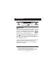
Safety Warnings TSTATBBNQ001 CAUTION Follow Installation Instructions carefully. DISCONNECT POWER TO THE HEATER AIR CONDITIONER BEFORE REMOVING THE OLD THERMOSTAT AND INSTALLING THE NEW THERMOSTAT. WARNING CAUTION The 2 Alkaline “AA” batteries must be replaced at least every 12 months to assure proper operation. The thermostat will display the Low Battery code (fig. 1) on the display of the thermostat when it is time to replace the batteries. FIG.
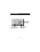
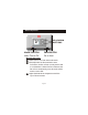
Location of Controls 72 MODE SWITCH Heat, Cool or Off UP & DOWN BUTTONS FAN SWITCH On or Auto Page 3
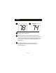
Display 78 74 SET TEMP Current room temperature. If the Up or Down arrow buttons are pressed the thermostat will show the desired Set Temp temperature indicator. Once this screen is reached you may use the Up or Down arrow buttons to adjust the desired room temperature. After five seconds with no button presses the thermostat will revert back to show the current room temperature.
Normal Operation 72 MODE SWITCH Heat, Cool or Off UP & DOWN BUTTONS FAN SWITCH On or Auto Manual Operation Select heat or cool with the mode switch. Normally leave the fan switched to auto. In fan auto, the fan will turn on only with a heat or cool demand. When Fan On is selected, the fan will run continuously, even when the mode switch is set to Off. Adjust the desired set temperature with the Up or Down buttons.
Step #1 72 Heat Off Cool Fan On FanAuto Proper installation of the thermostat will be accomplished by following these step by step instructions. If you are unsure about any of these steps, call a qualified technician for assistance.
Step #2 72 Heat Off Cool FanOn FanAuto 72 Heat Off Cool FanOn FanAuto 72 Heat Off Cool FanOn FanAuto 72 Heat Off Cool FanOn FanAuto Remove & Replace Old Thermostat Remove the cover of the old thermostat. If it does not come off easily check for screws. Loosen the screws holding the thermostat base or subbase to the wall, and lift away. Disconnect the wires from the old thermostat.
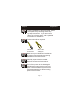
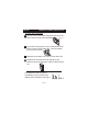
Step #3 Installation and Battery Replacement To Open The Thermostat The top of the thermostat housing has two (2) screwSCREWDRIVER driver slots to assist when seperating. SLOTS To pull the housing apart, insert a small blade screwdriver into the slot and rotate 90 . This will release the top housing snaps. Repeat the procedure in the other screw driver slot. Separate the housing halves by pulling the top forward until the pins release, and then lift the bottom out.
Battery Replacement REPLACE WITH ALKALINE BATTERIES AT LEAST ONCE EVERY YEAR, OR WHEN THE “LOW BATTERY” APPEARS (pages 2,8).
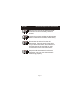
Step #4 72 Heat Off Cool FanOn FanAuto Wire Connections If the terminal designations on your old thermostat do not match those on the new thermostat, refer to the chart below, or the wiring diagrams that follow. Function Install on the new thermostat connector marked W1, W or H Heating W Y1 or Y Cooling Rev. Valve Y Wire from the old thermostat terminal marked B (Energize to Heat) B O Rev.
Sample Wiring Diagrams 4 Wire, 1 Stage Cooling, 1 Stage Gas Heat Residential Gas or Electric Heat *, Electric Cool, split systems & package units W Y B O G R FAN G COOLING Y GAS OR ELECTRIC HEAT W POWER R 4 Conductor 18 to 22 gauge unshielded cable from the thermostat to the equipment.
Sample Wiring Diagrams 4 Wire, 1 Stage Cooling, 1 Stage Heat-Heat Pump with O reversing valve*. Residential Heat Pumps, split systems & package units, with no auxiliary heat. W Y B O G R REVERSING VALVE O COMPRESSOR Y FAN G POWER R 4 Conductor 18 to 22 gauge unshielded cable from the thermostat to the equipment. * For Heat Pump or Electric Heat applications see page 17 or 18 for Jumper configuration.
Sample Wiring Diagrams 4 Wire, 1 Stage Cooling, 1 Stage Heat-Heat Pump with B reversing valve*. Residential Heat Pumps, split systems & package units, with no auxiliary heat. W Y B O G R FAN G REVERSING VALVE B COMPRESSOR Y POWER R 4 Conductor 18 to 22 gauge unshielded cable from the thermostat to the equipment. * For Heat Pump or Electric Heat applications see page 17 or 18 for Jumper configuration.
Sample Wiring Diagrams 3 Wire, 1 Stage Heat Residential Gas or Electric Heat units with a separately controlled fan. W Y B O G R POWER R FAN G GAS OR ELECTRIC HEAT W 3 Conductor 18 to 22 gauge unshielded cable from the thermostat to the equipment.
Sample Wiring Diagrams 2 Wire, 1 Stage Gas Heat Residential Gas or Millivolt units. W Y B O G R POWER R GAS OR ELECTRIC HEAT W 2 Conductor 18 to 22 gauge unshielded cable from the thermostat to the equipment.
Sample Wiring Diagrams 3 Wire, 1 Stage Cooling Residential Electric Cool units W Y B O G R FAN G COOLING Y POWER R 3 Conductor 18 to 22 gauge unshielded cable from the thermostat to the equipment.
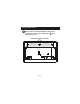
Step #5 Jumper Configuration Figure-A) FAN W/ HEAT J1 1 2 3 HEAT PUMP J2 3 2 1 72 Heat Off Cool Fan On FanAuto Jumper and Jumper are shown in the factory default positions for typical gas furnace heating with electric cooling.
Step #5 Jumper Configuration Figure-B) FAN W/ HEAT J1 1 2 3 HEAT PUMP J2 3 2 1 72 Heat Off Cool Fan On FanAuto Jumper is used to select Fan On (G) with Heat (W). Jumper shown in the factory default position.
Step #5 Jumper Configuration Figure-C) FAN W/ HEAT J1 1 2 3 HEAT PUMP J2 3 2 1 72 Heat Off Cool Fan On FanAuto Jumper and Jumper are used to select heat pump operation. Note: Thermostat Does Not Have Auxiliary Heat / Emergency Heat Capability. Leave jumpers in original factory default positions (figure-A) for non heat pump applications.
Step #5 72 Heat Off Cool Fan On FanAuto 72 Heat Off Cool Fan On FanAuto 72 Heat Off Cool Fan On FanAuto 72 Heat Off Cool Fan On FanAuto Test Operation Turn on the power to the Heating/Air Conditioning system. Adjust the Slide Switch until it is located under the word HEAT on the thermostat. Press the Up or Down buttons until the set temperature is 10 degrees above room temperature. The HVAC unit should energize in the heating mode (pages 4-5).
Troubleshooting 72 Heat Off Cool Fan On FanAuto 72 Heat Off Cool Fan On FanAuto SYMPTOM: The slide switches on the thermostat are very difficult to move. CAUSE: The backplate of the thermostat is deformed by being screwed tightly into a wall that is not perfectly flat. REMEDY: Loosen the screws holding the thermostat into the wall. SYMPTOM: The air conditioning does not attempt to turn on.
Troubleshooting 72 Heat Off Cool Fan On FanAuto SYMPTOM: The heating does not attempt to turn on. CAUSE: The heating setpoint is set too low or the Mode Switch is not set for Heat, or the batteries are too weak. REMEDY: Consult the Normal Operation section in this manuals to raise the heating setpoint and to correct the Mode Switch position, or replace the batteries (Page 9).
Warranty 5-Year Warranty - This Product is warranted to be free from defects in material and workmanship. If it appears within five years from the date of original installation, whether or not actual use begins on that date, that the product does meet this warranty, a new or remanufactured part, at the manufacturer’s sole option, to replace any defective part will be provided without charge for the part itself; PROVIDED the defective part is returned to the distributor through a qualified servicing dealer.