0B CROSSOVER OWNER’S MANUAL for Models 10B-STD, 10B-SUB & 10B-LR
INTRODUCTION: The 10B crossover is available in three stock versions; 10B-SUB incorporating frequencies more suitable to sub-woofer applications (40Hz to 500hz), 10B-STD which is more applicable to speakers requiring frequency control in the mid-band and tweeter areas (70Hz to 4500Hz) and the 10B-LR, which uses plug in resistor programming cards to set the crossover frequency.
POWER AMPLIFIERS: When power amplifiers of different power capabilities are used, the woofers will likely be driven by the most powerful amplifier and the tweeters by the least powerful amplifier since the woofers can generally be expected to be less efficient.
24g stranded, tinned copper conductors and locking XLR connectors with metal shells and gold plated contacts. Unbalanced cables use single conductor shielded co-axial cable with gold plated male phono (RCA) plugs in metal shells.
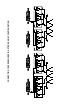
CONNECTING 10B CROSSOVERS IN A STEREO 4-WAY CONFIGURATION
RESISTOR/CAPACITOR SUBSTITUTION TABLES for PROGRAMMING CUSTOM CROSSOVER FREQUENCIES in LINKWITZ-RILEY (10B-LR) MODELS The resistors used to program specific crossover frequencies in the Linkwitz-riley filters are often installed directly on the 10B-LR main boards, but they can also be installed on small programming boards as shown in the illustration “10B-LR PROGRAMMABLE LINKWITZ-RILEY STEREO CROSSOVER”.
39 Hz 143K00 604K00 1M2100 38 Hz 147K00 619K00 1M2400 38 Hz 150K00 634K00 1M2700 37 Hz 154K00 649K00 1M3000 36 Hz 158K00 665K00 1M3300 35 Hz 162K00 681K00 1M3700 34 Hz 165K00 698K00 1M4000 33 Hz 169K00 715K00 1M4300 32 Hz 174K00 732K00 1M4700 32 Hz 178K00 750K00 1M5000 31 Hz 182K00 768K00 1M5400 30 Hz 187K00 787K00 1M5800 29 Hz 191K00 806K00 1M6200 29 Hz 196K00 825K00 1M6500 28 Hz 200K00 845K00 1M6900 27 Hz 205K00 866K00 1M7400 27 Hz 210K00 887K00 1M7800 26 Hz 215K00 909K00 1M8200 25 Hz 221K00 931K00 1M8700
IMPORTANT SAFETY INSTRUCTIONS The lightning flash with arrowhead symbol within an equilateral triangle, is intended to alert the user to the presence of un-insulated “dangerous voltage “ within the product’s enclosure that may be of sufficient magnitude to constitute a risk of electric shock to persons. The exclamation point within an equilateral triangle is intended to alert the user to the presence of important operating and maintenance (servicing) instructions in the literature accompanying the product.