6BSST POWER AMPLIFIER OWNER’S MANUAL
6BSST THREE CHANNEL POWER AMPLIFIER Table of Contents General Introduction Instalation and Ventilation Page 1 Rear Panel Input Settings/Connections Setting Input Selector Switch Balance Input Connector Configuration Setting Polarity Setting Input Sensitivity Page 2 Output Binding Posts and Polarity Page 3 Front Panel Description LED Indicators (Power-up Sequence) LED Indicators (Operating Conditions) Page 4 Power Control Panel Master Curcuit -Breaker AC Power Input Local/Auto Switch Local/External
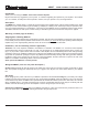
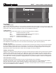
6BSST THREE CHANNEL POWER AMPLIFIER Introduction Thank you for choosing the 6BSST Three Channel Power Amplifier. Bryston welcomes any suggestions you may have, or comments regarding the operation of your amplifier. We consider you, our customer, to be Bryston’s most important resource, and your opinion is very much appreciated. Description The 6BSST is a modular design 3 x 300W per channel audio power amplifier. Each channel selects a balanced or single ended input.
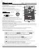
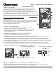
6BSST THREE CHANNEL POWER AMPLIFIER Rear Panel Input / Output Connections 1. Input Select Switch. Each 6BSST channel gives the user the option of switching between either balanced input or single ended input. 2. Balanced Input connector. ( Imp. 20k ) This input connector accepts standard ‘XLR’ or 1/4” TRS . Use quality, 100% shielded cables with gold plated connectors. ‘XLR’ type ‘TRS’ type ‘RCA’ type 3. Single Ended Input. ( Un-balanced input ) ( Imp.
6BSST THREE CHANNEL POWER AMPLIFIER 6. Output binding posts & polarity. The RED binding post is connected to the amplifier output. Connect to this post the (+) terminal on the loudspeaker. The BLACK binding post is connected to signal ground. Connect to this post the (-) terminal on the loudspeaker. When the polarity switch is set for 0 degrees (normal operation ) the output at the RED binding post is in phase with the input signal.
BSST THREE CHANNEL POWER AMPLIFIER 2 1 Front Panel 1. 'SST POWER' switch The front panel label 'SST POWER', is a touch sensitive membrane switch used to apply or remove a/c line power to the 6BSST circuitry. Push firmly the center of the switch until the power-up sequence begins. Push again and the 6BSST will power-down. ( Note: the rear circuit breaker must be on for the 6BSST to power-up) 2.
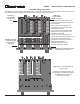
6BSST THREE CHANNEL POWER AMPLIFIER Power Control Panel 1. Master circuit - breaker. The 6BSST uses a magnetic-trip circuit breaker (1) to protect the amplifier. This switch should be ‘OFF’ when installing the 6BSST. When switched ‘OFF’ all A/C power is removed from the amplifier, including standby power. The circuit breaker is not the day to day power switch and should be switched and left ‘ON’ after the installation is complete.
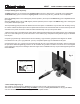
6BSST THREE CHANNEL POWER AMPLIFIER Rack Mounting Instructions The 6BSST 19” version may be rack mounted with or without the ability to remove the channels. If removal of the channels is desired then the shipping screws securing the channels need to be removed.
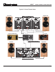
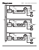
6BSST THREE CHANNEL POWER AMPLIFIER Typical 5.1 Home Theatre Setup Left Front 6BSST 3 x 300w per ch Powered Subwoofer Left Rear Right Front Center Home Theatre processor Right Rear 4BSST 2 x 300w per ch.
6BSST THREE CHANNEL POWER AMPLIFIER 8
6BSST THREE CHANNEL POWER AMPLIFIER Typical Band-pass Noise Power supply artifacts are all below -95 dBu balanced input with 23dB gain shown dBu: dB relative to a reference of 0.7746 Volts Typical THD+N Harmonic Content The harmonic content of the 6BSST is all even order.
6BSST THREE CHANNEL POWER AMPLIFIER Typical Frequency Response 8 ohm 300w<.01dB 20Khz. 4 ohm 500w<.1dB 20Khz.
6BSST THREE CHANNEL POWER AMPLIFIER Typical THD+N Sweep Graph shows that distortion is essentially unaffected by load. 4v balanced input shown.
6BSST THREE CHANNEL POWER AMPLIFIER Damping Factor 8 ohm reference Typical Crosstalk channel 2 reading with channels 1 & 3 driven to 300w into 8 ohms channel 2 reading with channels 1 & 3 driven to 600w into 4 ohms 12
6BSST THREE CHANNEL POWER AMPLIFIER Technical Specifications Power Output, Gain Select and Sensitivity 29dB - 1.7Vin = 300W @ 8 Ohms - (1V Position) 23dB - 3.4Vin = 300W @ 8 Ohms - (2V Position) 17dB - 6.8Vin = 300W @ 8 Ohms - (4V Position) Input Impedance 50 Kohms single ended 20 Kohms balanced Distortion IM or THD+noise < 0.005% 20Hz to 20kHz at 300 watts into 8 ohms, < 0.007% 20Hz to 20kHz at 500 watts into 4 ohms Noise Measured with input shorted - 20Hz to 20kHz.
IMPORTANT SAFETY INSTRUCTIONS The lightning flash with arrowhead symbol within an equilateral triangle, is intended to alert the user to the presence of un-insulated “dangerous voltage “ within the product’s enclosure that may be of sufficient magnitude to constitute a risk of electric shock to persons. The exclamation point within an equilateral triangle is intended to alert the user to the presence of important operating and maintenance (servicing) instructions in the literature accompanying the product.