SS E PR I 1 E S INSTRUCTIONS FOR BRYSTON SP1 PRECISION PREAMPLIFIER/PROCESSOR
For more information, call us today or visit our web site, 1-800-632-8216, www.bryston.
INTRODUCTION Congratulations on your purchase of the Bryston SP1 precision pre-amplifier/digital processor-decoder.This product will provide you with the finest available signal control and DSP audio processing available. Like all Bryston products the SP1 has been carefully designed and engineered to deliver a lifetime of enjoyment. Because the SP1 offers both pre-amplifier and digital decoding functions it is very important that you thoroughly read this manual BEFORE you install and use the SP1.
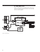
SP1 FUNCTIONAL LAYOUT Below is a block diagram of the Bryston SP1. It shows the signal flow and basic operational structure of the Surround Processor and Preamplifier.
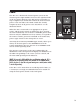
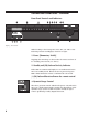
POWER The SP1 uses a dual mode electrical power system. In the electrical power input module located on the right hand side of the rear panel, adjacent to the IEC power cord socket is a large computer-style switch that controls the main electrical power to the unit.This is the ONLY switch that actually completely turns off all power to the unit. Please see the illustration below.
CONTROLS AND CONNECTIONS - OVERVIEW Front Panel Controls and Indicators Figure 3: Front Panel When looking at the front panel of the SP1 you will see the following controls and displays from left to right: 1. Power [Momentary Switch] Toggling this switch up or down takes the unit in and out of its' Standby power mode (see above) 2. Standby and (IR) Infrared Activity Indicator If this LED is continuously bright, it is an indication that the SP1 is in Standby mode.
A brief explanation follows: There are two variables built into many Dolby Digital bitstreams during the encoding process by the program producers, that can enable decoders like the SP1 to provide automatic gain control based upon the information supplied by these data variables. One of these two variables (labeled Dynrng by Dolby) provides a type of compression useful for situations such as late night viewing of programs with a wide dynamic range (like many action movies).
USING THE DYNAMIC RANGE CONTROL For the majority of applications this switch should be placed and remain in the middle or NORM position. For late night viewing or at any time you wish to reduce the overall dynamic range of a program the switch may be set to the "LATE" (down) position. If you wish to turn off all of the software's built-in dynamic range management functions the switch can be set to the "MAX" (up) position. NOTE: Caution should be exercised when choosing this option.
6. Menu Control Buttons These three buttons labeled "<", ">", and "SEL" (SELECT) are used to control the menu/setup functions displayed on the LCD. To enter a menu mode, you can press any one of these buttons. This will bring up the main menu. All of the SP1 set-up and calibration operations are done using these buttons and the LCD screen. Navigating any menu or sub-menu is done using the two arrow (< >) buttons.
Mode Selection Buttons: 8. Digital Mode and Indicator This button operates as a three way toggle function. The LED immediately above the button has two colors - RED and GREEN, and an OFF mode where it is not illuminated. When Digital Mode is selected, the decoder will automatically default to a digital signal for the selected input if one is present. If a digital signal is present and detected, the SP1 will automatically determine the type of bitstream and select the proper decoding mode.
10. Stereo and Stereo Downmix Mode If this button is selected and the supplied bitstream is more than 2 channels, the decoder will automatically implement a stereo downmix. Otherwise, analog or digital two channel signals are passed as conventional stereo. 11. Mono and Mono Downmix Modes If this button is selected and the supplied bitstream is more than 1 channel, the SP1 software will create a Mono mix of all signals.
13. THX Button Selecting this function (LED illuminated) will automatically incorporate the THX post processing option for all surround modes. (please SEE Appendix B FOR MORE Information) NOTE: When you choose to watch a DTS encoded DVD or LD movie, please be sure that the SP1 is in the DTS Movie mode. You may choose to use the THX features to enhance playback of DTS bitstreams for motion pictures. Sources originally mixed for a large environment such as motion pictures may benefit from THX processing.
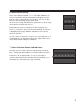
THE SP1 Rear Panel INPUT AND OUTPUT Connections 1. Balanced and 2. Unbalanced Outputs Figure 6: Rear Panel The SP1 offers both balanced and unbalanced outputs for power amplifiers or powered loudspeaker systems.The type you select to use will be determined by the input configuration of your amplifiers or self-powered loudspeakers. 3. Analog Inputs A paired stereo analog input with gold RCA jacks (labeled L and R, for Left and Right) is provided for each source button on the front panel.
Setting the Optical Audio Input Assignment i. Enter the main menu by pressing on one of the menu buttons on the SP1 front panel. Move the cursor to "OS". Hit 'Select' - You are now in the ‘Other Settings’ (Optical/THX) Menu. Figure 8: Highlight ‘OP1’ in the ‘Other Settings’ Menu ii. Move the cursor to the Optical Input (OPT1 or OPT2) you want to change the input assignment for. Hit ‘Select’. iii. Now you can assign the optical input to any one of the 6 inputs selectors.
Programming the AUX Trigger Output i. Enter the main menu by pressing on one of the menu buttons on the SP1 front panel. Move the cursor to "OS". Hit 'Select' - You are now in the Other Settings (Optical/THX) Menu. ii. Move the cursor to "T". (T = Trigger) Hit ‘Select’. Now you can assign the AUX Trigger output to ON or OFF, for each of the 6 input sources. Figure 9: Trigger Assign Menu iii. To change the source, use the "<" button.To toggle the trigger setting On or Off, use the ">" button.
The SP1 Remote Control Operating the SP1 from the Remote Control is similar to the front panel operation, with a few additions and omissions. 1. Source Select Buttons These buttons are used to select the desired source, and function exactly like their equivalent buttons on the front panel. 2. Mode Select Buttons These buttons are used to change the SP1 decoding mode, and function exactly like their equivalent buttons on the front panel. 3.
SET UP and CALIBRATION OF THE SP1 NOTE: In most operating menu modes the last segment of line 2 of the display will show an "X" for EXIT (a sample screen is shown below - fig 10). Choosing (highlighting) this position in the display and pressing the Select button (see below) will "EXIT" back to the previous menu or out of the particular menu or mode completely depending on where within the menu structure you are at the time. A more detailed explanation is given below in the section on menu control buttons.
System Setup and Configuration Setting the Speaker Configuration Before calibrating levels you must first tell the SP1 about your loudspeaker configuration.To do this: 1. First enter the main menu by pressing on any one of the menu buttons (< - > or SELECT). Figure 11: Setup Menu Figure 12: Speaker Configuration Menu 2. Next move the cursor to "SP". Hit 'SELECT' - You are now in the Speaker Menu. 3.
to effectively handle the low frequency dynamics of modern motion picture soundtrack sources such as DVD or HDTV feeds, and many other discrete multi-channel programming sources. If in any doubt choose small, especially if you are using a subwoofer, since this will insure that all the appropriate low frequency information is directed to the subwoofer where it can be most effectively handled.
Calibrating and Setting Levels / Channel to Channel Balance. 1. Position the Sound Level Meter at the Centre point of your listening area, at average ear height [ approximately 40 - 46 inches {102 - 117 cm.} with its microphone positioned vertically (pointing at the ceiling). DO NOT aim the sensing microphone at the speakers, as this will produce inaccurate level indications. 2. Using the SP1 Remote, press and hold for approximately 3-5 seconds the key labeled "Light - Hold for TEST".
3. Move the cursor to the speaker(s) you want to change the level for using the arrow keys (L, C, R, RS, LS, SUB). Hit 'SELECT'. Now you can adjust the Level for the selected speaker using the arrow buttons. 4. Hit ‘SELECT’ when finished, and repeat Step 3 to change the Level Trim for any of the other speakers. Setting the THX Subwoofer Limiter or "Bass Peak Level Manager" 1. Enter the main menu by pressing on one of the menu buttons. Move the cursor to "OS".
Setting the BPLM without Pink Noise To adjust the BPLM setting without running the Noise routine, Enter the BPLM as above, but when the SP1 prompts "Do BPLM Routine?", use the arrow keys to select ‘NO’ and hit ‘SELECT’. This will bring up the numeric value of the BPLM setting without the noise signal.You can now adjust the value using the arrow keys, and hit ‘SELECT’ when finished. Caution: If the BPLM is set to "OFF" or "0", the Bass Limiting function is disabled.
to left surround and right to right surround, creating essentially a giant Stereo image throughout your space.The Music mode delay settings have no effect in this mode.This works especially well on lots of pop/rock music and also for many recordings with good natural ambiance. Natural: This mode enhances basic stereo reproduction by using the inherent acoustics recorded within the source material. It is generally suitable for use with all kinds of music.
APPENDIX B - THX INFORMATION Below is a summary of issues and information related to the proprietary and patented THX processing incorporated used in the SP1.The available space cannot include all the available information on this topic.Therefore, if you want more information or wish to research the topic in more detail please use the THX website at WWW.THX.COM.The information below was condensed from documentation supplied by THX.
The SP1, contains special processing designed by THX to correct those errors and restore the appropriate tonal and spatial balance to a movie soundtrack, so that you can hear what the film's producer/director intended. This processing includes: 1. An Electronic Crossover Electronic Crossovers allow the use of the more typical residentially sized smaller main speakers by sending the bass signals to a separate subwoofer. With Dolby Pro Logic sources, only the main front channels pass through the crossover.
In a commercial Theatre, you don't detect this because the large number of surround speakers and the reflections within the room prevent your two ears from receiving equivalent signals. The THX Decorrelation Circuit discreetly changes the time and phase of one surround channel versus the other preventing your left and right ears from hearing identical signals, and helping to re-create the spacious and ambient sound you experience in a commercial Theatre.
BRYSTON 20-YEAR WARRANTY Bryston products are warranted to be free from manufacturing defects for a minimum of twenty years from the original date of manufacture. This includes parts, labour and return shipping to the first owner and all subsequent owners. Warranty coverage is automatic and commences with the original date of manufacture which is kept on file at Bryston.