
User manual


10
522
522
522
5.0 Audio Connections
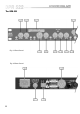
5.1 Main Inputs
There are 2 input sockets on the rear panel of the 522, Inputs 1 and 2. Each is
electronically balanced on standard 3 pin female XLRs at an impedance
greater than 10k Ohms. The ‘HOT, + or in phase’ connection is to pin 2 and
the ‘COLD, -, or out of phase’ connection is to pin 3. Pin 1 is internally
connected to the chassis earth via a low value capacitor. This ensures
freedom from ground loops whilst allowing good EMC performance. The
screen of the input cable should be connected to pin 1 to ensure that EMC
regulations are being met, and the cable shield ground should also be
connected to the equipment which is providing the input signal.
When feeding the DPR-522 from unbalanced sources, connect the signal
conductor to pin 2 and the cable screen to pins 1 and 3. Transformer isolated
inputs are available as a dealer fitted option.
Audio Connections
5.2 Main Outputs
The output signals are electronically balanced and fully floating on 3 pin
male XLRs. Full headroom is available into any load of 600 Ohms or greater.
The signal ‘HOT, +, or in phase’ signal is to pin 2, the ‘COLD, -, or out of
phase’ signal is to pin 3, with pin 1 being connected directly to the chassis.
Fig 5.1
Fig 5.2
Fig 5.3