V1.5 9 August 2006 Welcome Welcome to the MSR-602/604 II Users Manual This manual is provided to assist sound engineers, installers and consultants to fully understand the MSR-604 II and to benefit from its full capability. As opposed to most manuals, the contents can be read like a book. At the same time, the information is structured under a series of broad headings for easy access.
IMPORTANT SAFETY INSTRUCTIONS WARNING FOR YOUR PROTECTION READ THESE INSTRUCTIONS: CAUTION RISK OF ELECTRIC SHOCK DO NOT OPEN A T T E N T I O N : RISQUE DE CHOC ELECTRIQUE - NE PAS OUVRIR W A R N I N G : TO REDUCE THE RISK OF FIRE OR ELECTRIC SHOCK DO NOT EXPOSE THIS EQUIPMENT TO RAIN OR MOISTURE The symbols shown above are internationally accepted symbols that warn of potential hazards with electrical products.
IMPORTANT SAFETY INSTRUCTIONS U.K. MAINS PLUG WARNING ELECTROMAGNETIC COMPATIBILITY This unit conforms to the Product Specifications noted on the Declaration of Conformity. Operation is subject to the following two conditions: • this device may not cause harmful interference, and • this device must accept any interference received, including interference that may cause undesired operation. Operation of this unit within significant electromagnetic fields should be avoided.
MSR-600 II Series V1.5 9 August 2006 Welcome Welcome to the MSR-602/ 604 II Users Manual This manual is provided to assist sound engineers, installers and consultants to fully understand the MSR-604 II and to benefit from its full capability. As opposed to most manuals, the contents can be read like a book. At the same time, the information is structured under a series of broad headings for easy access.
Table Of Contents Table Of Contents 1.0 1.1 1.2 2.0 2.1 2.2 3.0 Introduction 4 MSR-604 II Mic/Line Signal Splitter MSR-602 II Power Supply Unit 5 6 Unpacking 7 Warranty Warning 7 7 Connections and Control Descriptions 8 3.1 3.2 3.3 3.4 3.5 4.0 AC power connections and control settings DC power connections Audio connections MSR-602 II Controls MSR-604 II Controls System Implementation and Use 4.1 4.2 4.3 4.4 4.5 4.6 4.7 5.
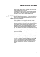
MSR-600 II Series Introduction 1.0 Introduction It is not uncommon within a sound system which uses microphones as a source of programme, for that microphone to be connected to the input of a number of different processing facilities. An example of this would be in sound reinforcement work where a stage microphone is required to drive the main ‘front of house’ mixing console, the stage monitoring mixing console, a mobile recording studio and quite possibly an outside broadcast recording vehicle.
MSR-604 II Microphone Signal Splitter flexibility of gain and level control, internal bus routing, signal metering and a headphone monitoring facility. The MSR-604 II is a four channel, four way signal splitting package and the MSR-602 II is the system power supply capable of supplying power for 20 channels, that is, 5 separate MSR-604 II units. 1.
MSR-600 II Series MSR-602 II Power Supply 1.2 MSR-602 II Power Supply The MSR-602 II is the system power supply providing all the necessary DC voltages for the MSR-604 II. It utilises a custom designed low field toroidal transformer and separate mumetal screen to reduce the possibility of mains field coupling into the electronic circuitry of the MSR-604 II.
Unpacking Warranty Warning 2.0 Unpacking As part of our system of quality control, this product is carefully inspected before packing to ensure flawless appearance. After unpacking the units, please inspect for any physical damage and retain the shipping carton and all relevant packing materials, should the unit require repacking. In the event that damage has occurred, immediately notify your dealer, so that a written claim to cover damages can be initiated. 2.
MSR-600 II Series Connections and Control Descriptions 3.0 Connections and Control Descriptions F10E F300MAL250V F3MAL250V F3MAL250V Fig.
AC Power Connections and Control Settings 3.1 AC Power Connections and Control Settings Before connecting the MSR-602 II to the AC power source, check that the voltage selector switch located on the rear panel is correctly set. If a change is necessary, ensure that the mains fuse is also changed for one of the correct rating. Before connecting the DC power leads, check that the system ground switch on the rear panel is also correctly set to ‘earthed’.
MSR-600 II Series Voltage Setting Safety EarthingAC Power Fusing Fig. 4 DC Connection Cabling 3.11 Voltage Setting The mains voltage selector switch provides simple, external adjustment for operation on all international AC power standards. At each switch position there is an acceptable tolerance over which the performance of the unit will not be affected and this is 90v-130v for the 120V position, and 180V-260V for the 240V position.
DC Power Connections Fig. 5 Cable Wiring Details ent connection of line to line rather than line to neutral phase voltages when using a three phase supply. In either case internal transient suppressors (VDRs) can become damaged and will consistently blow replacement fuses. You may be assured that they have protected your unit from damage, but they will need removal to allow further use of your unit, and should be replaced as soon as possible to ensure continued protection.
MSR-600 II Series Audio Connections 3.3 Audio Connections The audio connections to the MSR-604 II are via XLR style connectors on the front and rear panels and their wiring configuration is as shown in figure 5. Attention must be given to maintaining a consistent earthing system for safe and noise free operation. Please refer to section 4.2 for a fuller explanation and design guides.
MSR-602 II Controls Since all the audio connections are balanced, the convention of pin 2 or pin 3 ‘hot’ is of no consequence provided all connections are wired in a similar manner. Please refer to appendix B for details of the transformer balancing options. 3.4 MSR-602 II Controls SYSTEM GROUND: This switch, located on the rear panel, is the main grounding point for all the MSR-604 II units connected to the system.
MSR-600 II Series MSR-604 II Controls 3.5 MSR-604 II Controls PHANTOM ON/OFF The MSR-602 II power supply provides each MSR-604 II with 48v DC for phantom powering capacitor microphones. This is selected by operating the individual channel switch and it is connected across the ‘input’ connector in the standard phantom powering manner. Typical current availability is 10mA per channel for a 40 channel system. Phantom power is indicated by a front panel LED.
MSR-604 II Controls REMOTE ATTENUATOR A 10dB input pad is activated when the channel detects a +48v phantom signal is present on the MAIN OUTPUT. This allows the front of house mixing engineer to remotely reduce the input signal if he detects that the channel is being overdriven. This is a not uncommon occurrence in live rock and roll, when musicians get into the spirit of a performance and sing louder than during sound checks. A front panel LED indicates when REMOTE ATTENUATOR is active.
MSR-600 II Series System Implementation and Use Racking 4.0 System Implementation and Use 4.1 Racking It is envisaged that a number of the MSR-604 II units will be racked together with one MSR-602 II power supply. The metal case of the MSR-604 II is not connected to the electronic 0V, and is taken to the mains safety ground via its DC lead connection into Fig.
Racking the MSR-602 II. The MSR-602 II has a permanent safety ground connection via the power cord. Please read section 4.2 for discussion of grounding of the electronic 0v. The MSR-602 II power supply unit, unlike its predecessor has been designed for mounting at the TOP of a rack, above the MSR-604 II units it powers. In a properly installed MSR system mains induced hum from the PSU will be unmeasurable.
MSR-600 II Series Grounding Fig. 7 MSR Grounding 4.2 Grounding In any multi-channel audio system where low level signals are being routed, it is important to ensure a consistent and positive earthing system to minimise any possible noise interference and hum loops. With the use of microphones it is especially important to ensure reliable earthing and screening not only for these noise considerations but also for safety of the performers.
Channel Coding In general the stage monitor console will be connected to the stage mains power grounding system so the signal connecting cables to the ‘MON OUTPUT’ connector will require the earth connection to be disconnected. That is, the cable screening will be derived from the monitor console, but should not be connected to the electronic 0v earthing system of the MSR-604 II via pin 1 of the connector.
MSR-600 II Series Dual Power Supply Operation Output Drive Level Setting 4.4 Dual Power Supply Operation The power supply of the MSR-600 system performs a vital role within the sound system and although designed to exacting standards for ultimate reliability, some systems will require a back-up which would automatically take over on failure of the main supply. This is implemented within the MSR-600 system such that any two MSR602 II units can be directly connected together.
Fig. 11 Output Level Select Jumpers The permissible settings are shown in Figure 11, and the effects of each on system gain and headroom is described in Table 2. Note that combinations of header settings other than those shown should not be used as they do not give a proper balanced drive. TABLE 2 OUTPUT LEVEL SELECT HEADROOM AND GAIN STRUCTURE Setting 3dBm 13dBm 23dBu Output clip System gain Description Level /dB (Note 1) +3dBm 0 Mic level output.
MSR-600 II Series Multiple Output Distribution Amplifier Configuration Fig. 12 Bus Linking Block Diagram. Default Jumpers 4.6 Multiple Output Distribution Amplifier Configuration For use as a distribution amplifier, or in any situation where more than four outputs per channel are required, the MSR-604 II system may be reconfigured by moving internal jumpers. Up to sixteen adjacent channel sections, a total of sixty four outputs may be driven from a single input stage.
Multiple Output Distribution Amplifier Configuration Fig. 13A Bus Linking Ch1 Drives Out1 and 2 Ch3 Drives Out3 and 4 The signal labelled EXBUS-OUT passes via the LOOP OUT connector to the EXBUS-IN terminal in the LOOP IN connector on the adjacent unit, allowing a D.A. channel to span more than one MSR-604 II unit. It will be apparent from the above example that the permutations of D.A.
MSR-600 II Series Multiple Output Distribution Amplifier Configuration Stereo Summing Configuration Fig. 13B Bus Linking In1+In2 Drives Out1 and 2 In3+In4 Drives Out3 and 4 CONTROLS When a group of channels is linked as a D.A., the controls associated with the chosen input section are used to set the required operating conditions.
Compatibility With Pre MkII Systems Installing MSR-604 IIs in a Mk 1 System 5.0 Compatibility With Pre MkII Systems Limited compatibility exists between early MSR-604 systems and MSR604 II units using adaptor leads to interconnect the power cables. Please order adaptor leads as MSR-604 Mk I adaptor kit Z-MSRIIADK01. This pair of cables is required for any of the system combinations described below. Only one adaptor set is required per system no matter how many new units are to be to be installed. 5.
MSR-600 II Series Installing Pre Mk II MSR-604s Into a New System Installing a Mk II Power Supply Into a Mk I System and Vice Versa 5.2 Installing Pre Mk II MSR-604s Into a New System RACK INSTALLATION 5.3 Installing a Mk II Power Supply Into a Mk I System and Vice Versa 26 together as described in section 3.2. Finally the pair of adaptor leads are used to insert the Mk II units into the systems power circuit.
Appendix A System Block Diagram and Circuit Description 6.0 Appendix A 6.1 System Block Diagram and Circuit Description advice if a replacement or a second power supply is required for a Mk I system. Figure 14 shows the block diagram of the audio section of the MSR604 II. The DC supply regulator circuits (not shown) are common to all channels. The rails to each channel are protected by fusible resistors so that in the event of a short circuit fault in one channel the other three are not affected.
MSR-600 II Series Transient Suppressor Replacement balanced 10dB pad using a relay controlled by a circuit which monitors the MAIN OUTPUT XLR for the presence of phantom DC voltage. The balanced signal then passes through the optional input transformer, if fitted, and DC blocking capacitors to the low noise INPUT AMPLIFIER. This stage provides the common mode rejection trim, GAIN switch and provides a line level low impedance unbalanced drive signal to the BUS LINKING HEADERS.
Appendix B Input Transformer Balancing Output Transformer Balancing 7.0 Appendix B 7.1 Input Transformer Balancing Figure 15 indicates the location and specification for the suppressors. In some situations it might be necessary to provide a transformer balanced input and provision has been made within the MSR-604 II for it’s mounting. Please order as ‘MSR-604 II input transformer kit Z-MSRTXIII-01’. This is per channel, with four required for one MSR-604 II unit.
MSR-600 II Series Technical Specifications 8.0 Technical Specifications MSR-604 II Please order as ‘MSR-604 II balanced output transformer kit ZMSRTX0II-01’. This is per channel with four required for one MSR-604 II unit. Full fitting instructions are provided with this kit. Channels Four: Independant or internally interconnected Inputs XLR-3F Electronically balanced (Transformers optional) Microphone Line Impedance 2kΩ 10kΩ Max.
Technical Specifications Stereo/Mono Load Impedance Max output Level control 1/4in Jack socket 4Ω to 600Ω 1W rms -90dB to 0dB Power +/-27VDC, +48VDC from MSR-602 II PSU only Connectors 9 pin ‘D’, with lock jackscrews Weight 3.8kg Net Size 1.75" x 19" x 11.6" (44 x 482 x 293 mm) excluding connectors AC Input 90-130/180-260VAC 50/60Hz @ 150VAC 3 pin IEC with locking clip Connector Voltage selector Rear panel 120/240V Switch Rear panel High-inrush Rear panel T3.
MSR-600 II Series Technical Specifications Weight 7.0 kg Net Size 1.75" x 19" x 11.6" (44 x 482 x 293mm) excluding connectors Should you experience any difficulty in operating this equipment please contact your local dealer who will also be able to supply you with information on the full range of equipment manufactured by BSS Audio.
Warranty 9.0 Warranty Information This unit is warranted by BSS Audio to the original end user purchaser against defects in workmanship and the materials used in its manufacture for a period of one year from the date of shipment to the end user. Faults arising from misuse, unauthorised modifications or accidents are not covered under this warranty. No other warranty is expressed or implied.
MSR-600 II Series USER NOTES 34
USER NOTES 35
MSR-600 II Series USER NOTES 36