
Specifications
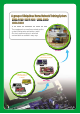
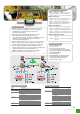
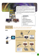

BCT-100 System Diagram
BCT-100 Functions
Items Specifications
MPU
Telecommunication
User Interface
I/O Ports
Others
BCT-100 Specifications
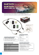
Main Package
Module Package
Accessories
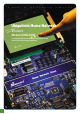
BCT-100 Components
BCT-100 (Client)
BCT-100 (Server)
BCT-100 (Client)
RS-232 Monitoring
Sensing
Control
Ethernet/ RS-485Network
( Server / Client Communication Protocol )
PC
BCT-100 (Client)
Digital I/O
Analog In
Relay Out
Infra-Red
Wired communication / monitoring
Remote control by Infrared RX/TX
220V AC, 5V DC On/Off control by Relay port
2 bit Digital In/Out port (Direct connection to MPU)
2 Channel Analog Input (Direct connection to MPU
2 Line Text LCD, 4 Push Keys, Buzzer, LED User
Interface support
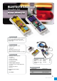
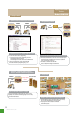
BCT-100 Features
BCT-100 Training Contents
PART 1. INTRODUCTION OF SYSTEM
PART 2. BASIC PRACTICE
PART 3. COMMUNICATION PRACTICE
PART 4. CONTROL PRACTICE
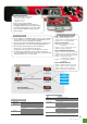
1. BCT-100 equipment uses ATMEGA128 MPU ( low-power, high-performance).
User can study micro-processor programming, embedded I/O control and
RS-485,RS-232, ethernet communication programming.
2. BCT-100 is developed to help embedded programming. This equipment has
many interesting devices. ( 2-line text LCD, LED, buzzer,Digital I/O port etc..)
3. BCT-100 supports RS-485/ Ethernet network communication
(Client/Server). So user can study many network issues
(encryption/error detection and so on..) and network control schemes.
4. Server/Client mode communication (and check status) is possible. Also,
user can develop/implement their own character (string, encrypted message)
sending program and error correction program.
45
www.manntel.com