
User's Manual
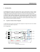
Table Of Contents
- Document History
- Revision History
- GENERAL SAFETY PRECAUTIONS
- TABLE OF CONTENTS
- LIST OF FIGURES
- LIST OF TABLES
- 1 Introduction
- Figure 1Block Diagram of Host Unit
- Figure 2 Block Diagram of Remote Node
- 2 Safety
- 3 System Overview and Unit Description
- Figure 3mBSC System Functional Overview
- Figure 4 Host Unit
- Figure 5BIU
- Figure 6FIU
- Figure 7 PSU
- Figure 8RCU
- Table 1 Host Unit User Interface
- Front Panel
- Rear Panel
- Figure 10Fiber CM-BTS/ANT Enclosure Outline
- Figure 11Fiber CM-BTS/ANT Interior Layout
- Table 6Fiber CM-BTS/ANT Enclosure User Interface
- Figure 12Fiber CM-BTS/ANT Enclosure User Interface
- Table 7Single-band BDA Enclosure User Interface
- Figure 14 Single-band RU Enclosure User Interface
- Table 8 Indicator Description
- Table 9Shroud Specification
- 4 System Installation
- Figure 17 Mounting Brackets for 19” Rack Installation
- Figure 18Host Unit-19” Rack Mounting View
- Figure 19Host Unit Grounding Stud
- Figure 20 Grounded Host Unit
- Figure 21 BTS QMA Coaxial Cable Connection
- Figure 23E2000 Fiber Optic Port on Host Unit FIU
- Figure 2448VDC Host Power Connection
- Figure 25IP Connection for local GUI Control
- Figure 26Modem Port on RCU (DB9 male)
- Figure 27 Mounting Panel Mounting
- Figure 28Mount the Remote Unit on the Mounting Panel
- Figure 30Grounding Stud
- Figure 31 Grounding Wire the Ring Terminal
- SMA Coaxial Cable Inter-connection on Fiber CM-BTS/ANT Enclosure
- SMA Coaxial Cable Inter-connection on Single-band Enclosure
- DIN(7/16) Coaxial Cable Inter-connection on Single-band RU Enclosure
- N Type Coaxial Cable Inter-connection on CM-ANT Enclosure
- Figure 34Fiber Optic Cable Connection to Fiber CM-BTS Enclosure
- Warning
- Figure 35 AC Power Junction Box
- Figure 364-Pin AC Power Connector
- Figure 39 Flow Chart of System Debugging
- 5 System Monitoring &Configuration
- Figure 40– EMS Local GUI Login
- Figure 41- Main Page Expanded Topology
- Figure 42- Main Page Summary View
- Figure 43- RCU Component View
- Figure 44- Main Page Equipment Status
- Figure 45- FIU Optical Power Levels
- Figure 46- CM Optical Power Levels
- Table 15System Alarms
- 6 Maintenance
- Figure 56Host Unit Trouble Shooting
- Figure 57Remote Unit Trouble Shooting
- 7 Terms, Acronyms & Abbreviations
- IC Radiation Exposure Statement
- IC Déclaration sur la radio exposition

MBSC0800-040-RU
MBSC0800-040-RU July 02, 2014
Page 1
1 Introduction
The MBSC0800-040-RU Fiber Optic Coverage System is used to extend wireless coverage to specific
areas in building(s), or throughout a complex zone. The mBSC product family offers a flexible, scalable,
modular platform to improve signal quality and enhance the services to meet the increasing demands.
The MBSC0800-040-RU system components include a Host Unit (HU) and a Remote Node. Each Host Unit
can feed up to eight multi-band Remote Nodes, each utilizing a single fiber. A Remote Node can
accommodate between one and five single-band bi-directional amplifiers (Remote Units) – install only the
bands required at the time of deployment. As requirements change, additional single-band units can be
easily installed in the field. This modular architecture provides optimum implementation flexibility, reduces
initial cost, and defers further investment until required.
1.1 System Solution Block Diagram
The MBSC0800-040-RU platform allows flexible system deployment to support mixed mode 700~2700MHz
services in SISO and/or MIMO configurations.
1.1.1 Host Unit
Figure 1Block Diagram of Host Unit
Band RF Signal Processing and
Filtering
E/O
Tx Gain &
Gain Ajustment
Tx Signal
Splitting
700
Rx Gain &
Gain Ajustment
Rx Signal
Combiner
E/O
E/O
Tx1
Downlink
Uplink
E/O
Tx2
Tx3
Tx4
Rx1
Rx2
Rx3
Rx4
BIU-I
FIU-I
PSU-I PSU-II RCU
0.7~2.6G
0.7~2.6G
FIU-II
HOST UNIT (4:1 Simulcast)
850
1900
2100
2600
700
850
1900
2100
2600
0.7~2.6G
0.7~2.6G