
User's Manual
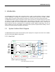
Table Of Contents
- Document History
- Revision History
- GENERAL SAFETY PRECAUTIONS
- TABLE OF CONTENTS
- LIST OF FIGURES
- LIST OF TABLES
- 1 Introduction
- Figure 1Block Diagram of Host Unit
- Figure 2 Block Diagram of Remote Node
- 2 Safety
- 3 System Overview and Unit Description
- Figure 3mBSC System Functional Overview
- Figure 4 Host Unit
- Figure 5BIU
- Figure 6FIU
- Figure 7 PSU
- Figure 8RCU
- Table 1 Host Unit User Interface
- Front Panel
- Rear Panel
- Figure 10Fiber CM-BTS/ANT Enclosure Outline
- Figure 11Fiber CM-BTS/ANT Interior Layout
- Table 6Fiber CM-BTS/ANT Enclosure User Interface
- Figure 12Fiber CM-BTS/ANT Enclosure User Interface
- Table 7Single-band BDA Enclosure User Interface
- Figure 14 Single-band RU Enclosure User Interface
- Table 8 Indicator Description
- Table 9Shroud Specification
- 4 System Installation
- Figure 17 Mounting Brackets for 19” Rack Installation
- Figure 18Host Unit-19” Rack Mounting View
- Figure 19Host Unit Grounding Stud
- Figure 20 Grounded Host Unit
- Figure 21 BTS QMA Coaxial Cable Connection
- Figure 23E2000 Fiber Optic Port on Host Unit FIU
- Figure 2448VDC Host Power Connection
- Figure 25IP Connection for local GUI Control
- Figure 26Modem Port on RCU (DB9 male)
- Figure 27 Mounting Panel Mounting
- Figure 28Mount the Remote Unit on the Mounting Panel
- Figure 30Grounding Stud
- Figure 31 Grounding Wire the Ring Terminal
- SMA Coaxial Cable Inter-connection on Fiber CM-BTS/ANT Enclosure
- SMA Coaxial Cable Inter-connection on Single-band Enclosure
- DIN(7/16) Coaxial Cable Inter-connection on Single-band RU Enclosure
- N Type Coaxial Cable Inter-connection on CM-ANT Enclosure
- Figure 34Fiber Optic Cable Connection to Fiber CM-BTS Enclosure
- Warning
- Figure 35 AC Power Junction Box
- Figure 364-Pin AC Power Connector
- Figure 39 Flow Chart of System Debugging
- 5 System Monitoring &Configuration
- Figure 40– EMS Local GUI Login
- Figure 41- Main Page Expanded Topology
- Figure 42- Main Page Summary View
- Figure 43- RCU Component View
- Figure 44- Main Page Equipment Status
- Figure 45- FIU Optical Power Levels
- Figure 46- CM Optical Power Levels
- Table 15System Alarms
- 6 Maintenance
- Figure 56Host Unit Trouble Shooting
- Figure 57Remote Unit Trouble Shooting
- 7 Terms, Acronyms & Abbreviations
- IC Radiation Exposure Statement
- IC Déclaration sur la radio exposition

MBSC0800-040-RU
© 1999-2014 Bravo Tech Inc.
4.2.6 Lightning Protecting and Grounding 24
4.3 HOST UNIT INSTALLATION 24
4.3.1 Rack Mounting 24
4.3.2 Cable Connections 26
4.4 REMOTE NODE INSTALLATION 30
4.4.1 Bracket and Shroud Installation 30
4.4.2 Cable Connections 33
4.5 INSTALLATION FINAL INSPECTION 38
4.5.1 Host Unit Connection Overview 39
4.5.2 Remote Node Connection Overview 40
4.5.3 mBSC-C Inspection Checklist 41
4.5.4 Cabling Inspection 41
4.6 SYSTEM TEST 41
5 SYSTEM MONITORING &CONFIGURATION 43
5.1 ACCESSING EMS LOCAL GUI 43
5.1.1 Using Ethernet Port 43
5.1.2 Using USB Port 44
5.1.3 Login to EMS Local GUI 45
5.2 NAVIGATING THE EMS LOCAL GUI 46
5.2.1 Topology Tool Bar 47
5.2.2 Upgrade/Password Functions 48
5.3 INSTALLATION & CONFIGURATION 48
5.3.1 Network & Communications 48
5.3.2 System Installation 50
5.3.3 Alarms 55
5.4 SYSTEM TUNING 57
5.4.1 BTS Signal Conditioning 57
5.4.2 Set Downlink Gain 57
5.4.3 Set Uplink Gain 60
5.4.4 Link Verification 61
5.5 MONITORING AND ALARMS 63
5.5.1 Operational Status 63
5.5.2 System Alarms 65
5.6 SYSTEM UPGRADE 66
5.6.1 Verify Software Versions 66
5.6.2 Upgrade component software 66