TECHNICAL GUIDE 04 Temperature control MH04/7G/GB
MY HOME TEMPERATURE CONTROL
General features CONTENTS MY HOME temperature control 4 Zone temperature control 6 The advantages of MY HOME temperature control 10 System examples 12 The solution for all types of system 15 Hydraulic system design 16 Application devices 19 Technical features Control unit 20 Sensor 22 2-relay actuator 23 4-relay actuator 24 Power supply 25 BUS wire 25 Pull-out terminals 25 Configuration Device configuration 26 Standard configuration 28 Quick configuration 41 Application e
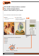
MY HOME temperature control The ideal temperature, when and where you want THE KEY ADVANTAGES OF ZONE TEMPERATURE CONTROL ■ COMFORT A different temperature profile in every room ■ UP TO 30% SAVING Depending on the type of system saving on consumption pays for the system in a few years WITH ALL THE ADVANTAGES OF A MY HOME SOLUTION ■ FLEXIBILITY ■ SIMPLICITY ■ FITTING IN ■ SECURITY MY HOME 4 MY HOME TEMPERATURE CONTROL TEMPERATURE CONTROL UNIT
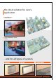
The ideal solution for every application ■ TERRACED HOUSE ■ LARGE HOME ■ SMALL COMMERCIAL SECTOR ■ OFFICE …and for all types of system GENERAL FEATURES CATALOGUE MY HOME TEMPERATURE CONTROL 5
Zone temperature control The guarantee of comfort… ■ THE TEMPERATURE PROFILE YOU WANT • For every room • For every day of the week From the morning... 7:00 22°C in the bedroom 16°C in the living room T3 T2 T1 0 6 12 18 24 T3 T2 T1 0 19°C in the kitchen 6 12 18 24 22°C in the bathroom T3 T2 T1 0 6 12 18 24 T3 T2 T1 0 6 12 18 24 ...
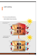
…and saving ■ UP TO 30% SAVING ON CONSUMPTION • You can turn off the rooms you do not use • The heat supplied by the sun is not wasted • The fan-coil speed is adjusted automatically The sun heats some of the house zones...
Zone temperature control Traditional solution ■ TOO MANY TIMER THERMOSTATS TO PROGRAM ■ YOU DO NOT CONTROL THE WHOLE SYSTEM ■ CANNOT BE USED IN LARGE SYSTEMS 8 MY HOME TEMPERATURE CONTROL
Zone temperature control MY HOME solution ■ JUST ONE CONTROLLER TO PROGRAM ■ EFFECTIVE CONTROL OF THE WHOLE SYSTEM ■ ALSO SUITABLE FOR LARGE SYSTEMS GENERAL FEATURES CATALOGUE MY HOME TEMPERATURE CONTROL 9
The advantages of MY HOME temperature control ■ SAVING AND COMFORT • zone temperature control allows different profiles for each room and for every day of the week. • depending on the type of system can save up to 30%.
■ LOCAL CONTROL In each room there is a sensor to measure the temperature which can also control the system simply: • ± 3°C with respect to the set-point • switch off the system • set the antifrost ■ CENTRALISED CONTROL OF THE WHOLE SYSTEM (UP TO 99 ZONES) Thanks to the temperature control unit the whole system can be controlled with a single command. It is like having 99 timer thermostats in a single device.
Heating system examples TERRACED HOUSE WITH RADIATOR HEATING ■ TRADITIONAL RADIATOR store-room kitchen bedroom Zone solenoid valves collector Kitchen Bedroom living room Store-room Living-room box 12 MY HOME TEMPERATURE CONTROL
LARGE HOUSE WITH RADIANT PANEL HEATING ■ RADIANT PANELS store-room kitchen bedroom Zone solenoid valves collector living room living room bedroom kitchen/ store-room box GENERAL FEATURES CATALOGUE MY HOME TEMPERATURE CONTROL 13
Heating and cooling system examples OFFICE WITH FAN-COIL HEATING AND COOLING ■ FAN-COIL FOR HEATING AND COOLING office 2 office 1 office 3 Zone solenoid valves collector office 2 office 3 office 1 box 14 MY HOME TEMPERATURE CONTROL
My Home temperature control The solution for all types of system ■ HEATING • radiators • fan-coil • radiant panels TRADITIONAL RADIATORS FAN-COIL RADIANT PANELS • 2 and 4 tubes • 3 speeds ■ COOLING • fan-coil FAN-COIL • 2 and 4 tubes • 3 speeds GENERAL FEATURES CATALOGUE MY HOME TEMPERATURE CONTROL 15
Hydraulic system design TYPE OF SOLENOID VALVE In a hydraulic system the zones are built up physically using solenoid valves. Each zone can thus be managed independently by controlling the individual solenoid valves.
Installing the solenoid valve in a 2-tube fan-coil M Installing the solenoid valve in a 4-tube fan-coil M GENERAL FEATURES CATALOGUE MY HOME TEMPERATURE CONTROL 17
Designing a hydraulic system PLACING THE SOLENOID VALVES IN RADIANT PANEL SYSTEMS Radiant panel systems are always managed in zones and their solution is very similar to that of radiator systems. The zones are built up by means of solenoid valves grouped on the collector, but there is also a water mixture valve. This valve is proportional and cannot be controlled by the My Home temperature control.
MY HOME temperature control APPLICATION DEVICES A My Home temperature control system can manage up to 99 zones. The system is on a 2-wire bus and made up of the following devices: Temperature control unit: this configures the system, customises the programs and displays information. Sensors: at least one sensor must be installed in every zone. They measure the room temperature and can locally vary the temperature set on the control unit. Actuators: operate the solenoid valves and the circulation pumps.
Technical features TEMPERATURE CONTROL UNIT ITEM 3550 The Control unit, which can only be used for the BTicino temperature control function, can set the system and modify the system mode of operation.
GRAPHIC DISPLAY In normal working conditions the Control unit display shows the following information on the initial page: Mode of operation Name of the program being run Weekly Settimanale Example Esempio Winter Inverno Wed. Mer. 01 01Oct Ott 0000: : 01 01 Date State: Winter (heating) Summer (Cooling) Hour NAVIGATION KEYPAD The scroll keys scroll through the list of items in the menu.
Technical features SENSOR ITEM L/N/NT4692 The device can adjust the room temperature according to the daily routines in both winter and summer, varying the settings locally with respect to those received from the control unit. The item has a knob for the local temperature selection (limited to ± 3°C with respect to the value set by the control unit), the antifrost mode and the OFF mode. There are two LED, one green and one yellow, on the front of the item.
2-RELAY ACTUATOR ITEM F430/2 By means of internal relays, this device executes the commands received from the control unit or the sensor. It is needed to control loads such as motorised valves, pumps and electric radiators. It has two independent relays which can be used to command two distinct loads with ON/OFF function and to command a single load with open/close function.
Technical features 4-RELAY ACTUATOR ITEM F430/4 By means of internal relays, this device executes the commands received from the control unit or the sensor. It is needed to control loads such as 3speed fan-coils, motorised valves, pumps and electric radiators. It has four independent relays which can be used to command two distinct loads with ON/OFF function and to command a single load with open/close function.
POWER SUPPLY ITEM E46ADCN Power supply with output in very low safety voltage (SELV) protected against short-circuit and overload. It supplies the functional power supply to the system components via the telephone wire. TECHNICAL FEATURES Power supply: 230V a.c. ± 10% 50/60Hz Max absorption: 300 mA Maximum current supplied: 1.2A Rated output voltage: 27V d.c. Size: 8 DIN modules 230V a.c.
Configuration DEVICE CONFIGURATION The sensors and actuators must be correctly configured so that they can perform the function required. In practice to configure means defining: For the sensors: 1 the relevant zone, within the Temperature control function 2 the pump control mode 3 the mode of operation (heating, cooling, etc.) 4 the pump switching on delay (if necessary) SENSOR CONFIGURATION For the actuators: a) the relevant zone b) the type of load to manage.
DEVICE CONFIGURATION To understand the addressing logic it is useful to define some frequently occurring terms. Sensor address The sensors also have positions [ZA] and [ZB] to define the address of the devices which will receive the command (actuators). These positions have numerical configurators which enable the device to send the command. Zone [ZA] and [ZB] Address of the devices belonging to a logic zone; as an example in a dwelling one can talk about night area, day area and cellar.
Standard configuration Sensor item L/N/NT4692 Each sensor is always configured by inserting two configurators which identify the sensor address, i.e. the number of the zone controlled by the sensor itself, in sockets [ZA] and [ZB]. The actuators controlled by this sensor must be configured with the same zone address.
In some types of system one or more water circulation pumps must be commanded, as well as commanding the zone valves. This control is not necessary in the following cases: The pump management is thus linked to the type of system made and in particular to the number of circulation pumps and solenoid valves used to control the single zone. Principally one can identify two types of solenoid valve: with limit switch and without limit switch.
Standard configuration Sensor item L/N/NT4692 USE OF SOCKET [P] • If the circulation pump must be controlled for both the heating function and the cooling function and the two functions will use the same pump, insert configurator 1 in [P]. Then connect the pump to an actuator configured in zone 00 ([ZA] = 0, [ZB] = 0) and put configurator 1 in socket [N] (see actuator configuration).
SEVERAL CIRCULATION PUMPS There may be several circulation pumps, which serve different groups of zones, in the same system. SOLENOID VALVE WITH LIMIT SWITCH to the pump in parallel. No sensor configuration is required. The valve is managed by its actuator. Traditional wiring must be installed to manage the pumps, connecting the limit switch contacts of the zone valves 1 2 3 4 1 2 3 4 ART.F430/2 C1 C2 BUS ZONE 1 .
Standard configuration Sensor item L/N/NT4692 SOLENOID VALVE WITHOUT LIMIT SWITCH When the solenoid valves do not have limit switches a two-relay actuator must be used for each zone (item F430/2), using one relay to manage the valve and the other relay to manage the pump belonging to the unit. For each actuator belonging to the same group of zones the pump contacts must be connected in parallel. No sensor configuration is required. , C1 1 2 3 4 1 . 2 3 4 ART.
Standard configuration 2-relay actuator F430/2 The item is configured by inserting two configurators which identify the actuator address, i.e. the number of the relevant zone, in sockets [ZA] and [ZB]; practically the operation is the same as that performed for the sensor in the zone definition phase. A sensor and an actuator which belong to the same zone will have the same numerical configurators in sockets [ZA] and [ZB].
Standard configuration 2-relay actuator F430/2 EXAMPLE Configuration and connection of the 2-relay actuator to control two solenoid valves (ON/OFF type) in two different zones (zone 1 and zone 2). The progressive number in the zone is 1. 3 LEGEND 1 actuator 2 solenoid valve zone 1 3 solenoid valve zone 2 4 radiator zone 1 5 radiator zone 2 2 5 1 1 2 3 4 1 2 3 4 C1 4 BUS ART.F430/2 .
EXAMPLE Configuration and connection of the 2-relay actuator to control a zone pump (in zone 7). The progressive number in the zone is 1. As relay RL2 is not used it is excluded. 3 2 4 LEGEND 1 actuator 2 check valve 3 pump zone 7 4 radiant panel 1 N 1 2 3 4 1 2 3 C1 4 ART.
Standard configuration 2-relay actuator F430/2 EXAMPLE Configuration and connection of the 2-relay actuator with interlock to control a solenoid valve with opening and closing command in zone 16. L C1 1 2 3 4 1 2 3 OPEN 4 N ART.
Standard configuration 4-relay actuator F430/4 As for the two-relay actuator two configurators which identify the actuator address, i.e. the number of the relevant zone, must be inserted in sockets [ZA] and [ZB]. A sensor and an actuator which belong to the same zone will have the same numerical configurators in sockets [ZA] and [ZB]. On the front part of the four-relay actuator there are six sockets for configurators: [ZA], [ZB1], [ZB2], [ZB3], [ZB3] and [N].
Standard configuration 4-relay actuator F430/4 EXAMPLE Configuration and connection of the 4-relay actuator to control four solenoid valves (ON/OFF type) in four different zones (zone 11, zone 12, zone 15 and zone 18). The zone progressive number is 1. 5 4 9 3 8 2 7 C1 1 LEGEND 1 actuator 2 solenoid valve zone 11 3 solenoid valve zone 12 4 solenoid valve zone 15 5 solenoid valve zone 18 6 radiator zone 11 7 radiator zone 12 8 radiator zone 15 9 radiator zone 18 6 C2 1 2 3 4 5 1 2 3 4 5 ART.
EXAMPLE Configuration and connection of the 4-relay actuator with interlock to control two solenoid valves with opening and closing command in zones 2 and 3. The progressive number in the zone is 2. M LEGEND 1 actuator 2 solenoid valve zone 2 3 solenoid valve zone 3 4 radiator zone 2 5 radiator zone 3 2 4 C1 OPEN 1 C2 1 2 3 4 5 1 2 3 4 5 ART.
Standard configuration 4-relay actuator item F430/4 EXAMPLE Configuration and connection of two 4-relay actuators (one for cooling and one for heating) to control a three-speed 4-tube fan-coil. For both actuators the zone is 28. The progressive number for the actuator intended for the cooling is 5, while for the actuator intended for the heating it is 6.
Quick configuration If the Temperature control function is used to manage a simple system there is no need to interact with the control unit via “Configure zones” in the “Maintenance” menu – just insert the configurators in the devices. A simple system is defined as a system which for each zone has just one actuator for heating and/or one actuator for cooling. In essence a simple zone has an actuator which only controls ON/OFF loads (solenoid valves, pumps, single-speed fan-coils and electric radiators).
Quick configuration HEATING AND COOLING ZONE Sensor configuration: • insert configurator 2 in socket [MOD]; • insert the configurators corresponding to the zone number in sockets [ZA] and [ZB]. Cooling actuator configuration: • insert configurator 2 in socket [N]; • insert the configurators corresponding to the zone number (the same as those inserted in the sensor) in sockets [ZA] and [ZB].
USING THE SENSOR SOCKET [P] • If control of the circulation pump is not required no configurator should be inserted in the socket. • If the circulation pump must be controlled either for the heating function or for the cooling function and the same pump will be used for the two functions, insert configurator 1 in [P]. Then connect the pump to an actuator configured in zone 00 ([ZA] = 0, [ZB] = 0) and insert configurator 1 in socket [N] (see actuator configuration).
Application examples SYSTEM DIAGRAM 4-zone large house with heating using radiators F430/4 2 ZONE 4 ZONE 3 F430/2 3 ZONE 2 ZONE 1 1 L 4 LEGEND 1 circulation pump 2 zone solenoid valve actuator 3 circulation pump actuator 4 boiler 44 MY HOME TEMPERATURE CONTROL BUS Traditional cable Hydraulic pipe
SENSOR CONFIGURATION [MOD] = not configured: just one actuator for heating in each zone Sensor zone 1 [ZA] 0 [ZB] 1 [P] 2 [MOD] [SLA] [DEL] [MOD] [SLA] [DEL] [MOD] [SLA] [DEL] [MOD] [SLA] [DEL] [ZB3] 3 [ZB4] 4 [N] 1 [P] = 2: heating only Sensor zone 2 [ZA] 0 [ZB] 2 [P] 2 Sensor zone 3 [ZA] 0 [ZB] 3 [P] 2 Sensor zone 4 [ZA] 0 [ZB] 4 [P] 2 ACTUATOR CONFIGURATION Zone actuator [ZA] 0 [ZB1] 1 [ZB2] 2 [N] = 1: heating actuator Circulation pump actuator [ZA] 0 [ZB1] 0 [N1]
Application examples SYSTEM DIAGRAM 4-zone large house with heating using 2 pumps with solenoid valves without limit switches, and radiators.
SENSOR CONFIGURATION [MOD] = CEN: there is more than one actuator per zone Sensor zone 1 [ZA] 0 [ZB] 1 [P] [MOD] CEN [SLA] [DEL] [MOD] CEN [SLA] [DEL] [MOD] CEN [SLA] [DEL] [MOD] CEN [SLA] [DEL] [P] = not configured: circulation pumps managed by actuators but with traditional wiring Sensor zone 2 [ZA] 0 [ZB] 2 [P] Sensor zone 3 [ZA] 0 [ZB] 3 [P] Sensor zone 4 [ZA] 0 [ZB] 4 [P] ACTUATOR CONFIGURATION Zone 1 actuator [ZA] 0 [ZB1] 1 [N1] 1 [ZB2] 1 [N2] 2 [N1] 1 [ZB2] 2 [N2
Application examples SYSTEM DIAGRAM 6-zone large house with heating using radiant panels.
SENSOR CONFIGURATION Sensor zone 1 [ZA] 0 [ZB] 1 Sensor zone 5 [P] 2 [MOD] [SLA] [DEL] Sensor zone 2 [ZA] 0 [ZB] 2 [ZB] 3 [ZB] 5 [P] 2 [MOD] [SLA] [DEL] [MOD] [SLA] [DEL] Sensor zone 6 [P] 2 [MOD] [SLA] [DEL] [ZA] 0 [ZB] 6 [P] 2 [MOD] = not configured: just one heating actuator in each zone Sensor zone 3 [ZA] 0 [ZA] 0 [P] 2 [MOD] [SLA] [DEL] [MOD] [SLA] [DEL] [ZB4] OFF [N] 1 [ZB4] OFF [N] 1 [P] = 2: heating only Sensor zone 4 [ZA] 0 [ZB] 4 [P] 2 ACTUATOR CONFI
Application examples SYSTEM DIAGRAM 8-zone large house with heating using radiators and fan-coil cooling.
HEATING Wiring diagram for connecting the solenoid valves of zones 2, 4, 6 and 8 to the heating actuator. To control zones 1, 3, 5 and 7 replicate the same connection between the solenoid valves and the corresponding actuator. The configuration must be made correctly, maintaining the correlation between ZONE 8 the actuator contact and the address of the zone to be controlled. In the example given here, zone 2 is controlled by contact C1 configured with [ZA] = 0 and [ZB] = 2.
Application examples SENSOR CONFIGURATION Sensor zone 1 [ZA] 0 [ZB] 1 [P] 4 Sensor zone 5 [MOD] CEN [SLA] [DEL] [P] = 4: two separate pumps, one for cooling and one for heating [ZA] 0 [ZB] 2 [P] 4 [MOD] CEN [SLA] [DEL] [ZB] 3 [P] 4 [MOD] CEN [ZB] 4 [P] 4 [ZA] 0 [SLA] [DEL] [ZA] 0 [MOD] CEN [ZB4] 8 [N] 1 [ZB4] 7 [N] 1 Zone 2, 4, 6 and 8 actuator [ZB1] 2 [ZB2] 4 [ZB3] 6 Zone 1, 3, 5 and 7 actuator [ZA] 0 52 MY HOME TEMPERATURE CONTROL [ZB1] 1 [ZB2] 3 [MOD] CEN [SLA] [D
COOLING SYSTEM ACTUATOR CONFIGURATION Zone 1 cooling actuator [ZA] 0 [ZB1] 1 [ZB2] 1 [ZB3] 1 Zone 5 cooling actuator [ZB4] 1 [N] 2 Zone 2 cooling actuator [ZA] 0 [ZB1] 2 [ZB2] 2 [ZB3] 2 [ZB1] 3 [ZB2] 3 [ZB3] 3 [ZB4] 2 [N] 2 [ZB1] 4 [ZB2] 4 [ZB3] 4 [ZB2] 5 [ZB3] 5 [ZB4] 5 [N] 2 [ZA] 0 [ZB1] 6 [ZB2] 6 [ZB3] 6 [ZB4] 6 [N] 2 [ZB4] 7 [N] 2 [ZB4] 8 [N] 2 Zone 7 cooling actuator [ZB4] 3 [N] 2 Zone 4 cooling actuator [ZA] 0 [ZB1] 5 Zone 6 cooling actuator Zone 3 cooling act
Application examples SYSTEM DIAGRAM Commercial sector, 12 zones, with fan-coil with two tubes and three speeds, single system for heating and cooling.
HEATING AND COOLING Wiring diagram for connecting the fan-coil to the actuator for zone 12 heating/cooling. To control the fan-coils belonging to all the other zones replicate the same connection, correctly configuring the actuator corresponding to the zone as indicated in the configuration tables.
Application examples HEATING SYSTEM FAN-COIL ACTUATOR CONFIGURATION Zone 1 actuator [ZA] 0 [ZB1] 1 Zone 7 actuator [ZB2] 1 [ZB3] 1 [ZB4] 1 [N] 1 Zone 2 actuator [ZA] 0 [ZB1] 2 [ZB1] 3 [ZB2] 2 [ZB3] 2 [ZB4] 2 [N] 1 [ZB1] 4 [ZB2] 3 [ZB3] 3 [ZB4] 3 [N] 1 [ZB1] 5 [ZB3] 4 [ZB4] 4 [N] 1 [ZB1] 6 [ZB2] 5 [ZB3] 5 [ZB4] 5 [N] 1 [ZB2] 6 [ZB3] 6 [ZB4] 6 [N] 1 Circulation pump actuator 56 MY HOME TEMPERATURE CONTROL [ZB1] 0 [N] 1 [ZA] 0 [ZB1] 8 [ZB2] 8 [ZB3] 8 [ZB4] 8 [N] 1 [
SENSOR CONFIGURATION Sensor zone 1 [ZA] 0 [ZB] 1 [P] 1 Sensor zone 7 [MOD] CEN [SLA] [DEL] [P] = 1: 1: control of a single pump for cooling and one for heating [ZA] 0 [ZB] 2 [P] 1 [MOD] CEN [SLA] [DEL] Sensor zone 3 [ZA] 0 [ZB] 3 [P] 1 [ZB] 4 [P] 1 [MOD] CEN [SLA] [DEL] [MOD] CEN [SLA] [DEL] [ZB] 5 [P] 1 [ZB] 6 [P] 1 [SLA] [DEL] [ZA] 0 [ZB] 8 [P] 1 [MOD] CEN [SLA] [DEL] [ZA] 0 [ZB] 9 [P] 1 [MOD] CEN [SLA] [DEL] [ZA] 1 [ZB] 0 [P] 1 [MOD] CEN [SLA] [DEL] [MOD
General installation rules PREPARING THE BUILDING Installation of Temperature control items does not interfere with the concepts of traditional systems but requires taking some precautions in the design phase. The BUS cable can share the trunking used for the traditional energy line, made with traditional concealed trunking or with trunking for wall mounting. This solution allows quicker installation and less work on the wall structure.
MAXIMUM NUMBER OF DEVICES A system can manage up to 99 zone addresses. Up to nine addresses dedicated to the actuators can be managed for each zone. The maximum number of devices which can be connected to the BUS also depends on their total absorption and the distance between the connection point and the power supply. The power supply can supply up to 1.
General installation rules EXTENSIVE SYSTEMS In large systems or systems which have current absorption greater than the limit of 1200 mA supplied by the power supply item E46ADCN, the system must be divided into several sections each supplied with its own power supply and connected by means of interface item F422 configured in “physical expansion” mode. It must be shown that the system limits, in terms of absorption and maximum wiring distance, as shown in this guide, are applied for each bus.
COMBINING WITH OTHER FUNCTIONS The Temperature control function devices can share the same BUS cable as other My Home automation and emergency management applications (grey cable). If there is already a stable cable with the automation or power management BUS the Temperature control items can be added at any point in the system, after installing a box item 503E for the control unit item 3550, one or more boxes positioned at a height of 1.
General installation rules TEMPERATURE CONTROL UNIT ITEM 3550 The Temperature control unit can be installed in two different ways: wall mounted or flush mounted. Wall installation requires the use of the metal base fastened to the wall by means of flush-mounting box 503E. By means of the trunking the flush-mounting box contains the wires for connection to the BUS and possibly for the remote control. The control unit can also be installed in Multibox series flush-mounted units.
SENSOR ITEM L/N/NT4692 As required the sensor can be installed in either normal flush-mounted or wall-mounted containers. For both solutions the installation height must be about 1.5 metres from the floor and away from zones which could influence the temperature reading. Wall installation may be useful to solve the problem of already existing BUS systems which cannot be expanded. This type of container avoids the need for wall work and is available in both Living International and Light series.
General installation rules ACTUATORS ITEM F430/2 ITEM F430/4 The actuators are made in two DIN module containers and feature the advantage that the rear adapter and the front cover can be removed so that they take up less room – e.g. to allow installation inside junction boxes. In installations in units the DIN adapter and the front cover mean that the profile of the actuator can be aligned with that of other DIN modular devices.
INSTALLING THE ACTUATORS IN A UNIT, NEAR THE SOLENOID VALVES AND COLLECTOR When the zone interceptions are made by means of solenoid valves or pumps installed in the same box as the collector all the actuators should be collected together in a unit which is installed near the box itself. solenoid valve actuators 1 2 3 4 1 2 3 4 1 2 3 4 1 2 3 4 ART.F430/2 C1 C2 1 2 3 4 1 2 3 4 ART.F430/2 C1 C2 1 2 3 4 1 2 3 4 ART.F430/2 C1 C2 ART.
Catalogue CONTROL UNIT Item 3550 Description control unit to manage the temperature control system BATTERY Item 3507/6 3550 Description 6V 0.
CONFIGURATORS – SINGLE-TYPE 10 PIECE PACKAGE 3501/0 3501/7 3501/1 3501/8 3501/2 3501/9 3501/3 3501/4 3501/CEN 3501/5 3501/6 3501/SLA 3501/OFF Item 3501/0 3501/1 3501/2 3501/3 3501/4 3501/5 3501/6 3501/7 3501/8 3501/9 3501/OFF 3501/SLA 3501/CEN Description configurator 0 configurator 1 configurator 2 configurator 3 configurator 4 configurator 5 configurator 6 configurator 7 configurator 8 configurator 9 configurator OFF configurator SLA configurator CEN CONFIGURATOR KIT Item 346900 3501K/1 346900 Descrip
BTicino SpA Bticino reserves the right to change the contents in this printed brochure at any time. Edition 09/2004 Via Messina, 38 20154 Milano - Italy www.bticino.