
Installation manual


LEGEND
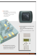
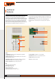
1) Graphic display: shows the messages which guide the programming
operations and the system state.
2) Navigation keypad: allows navigation within the menus and confirms or
deletes programming operations.
3) Alphanumeric keypad: allows manual entry of all those programming
operations which require the use of numbers and/or symbols.
4) Battery compartment: housing for battery item 3507/6.
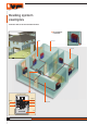
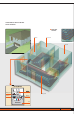
The Control unit, which can only be used for the BTicino temperature
control function, can set the system and modify the system mode of
operation. Equipped with management software with guided menus shown
on the display, it allows the user to chose the mode of operation, display
the temperatures of the various zones and display and modify the daily
temperature profi les and the weekly programs, while the maintenance
menu, reserved for the installer (password protected), allows access to the
system settings (zone confi guration, system test, total reset, etc.).
TEMPERATURE CONTROL UNIT ITEM 3550
1
2
3
DATA
Power supply: from 18V to 28V BUS
Maximum absorption: 75 mA
Size: L = 140 H = 210 D = 35
Degree of protection: IP30
Operating temperature: from 5°C to 40°C
Temperature setting: from 5°C to 40°C ± 0.5°C
Technical
features
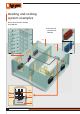
The Control unit can provide both heating and cooling and can manage up to
99 different zones (with a Master sensor and/or detector for each zone plus
any Slave detectors).
A contact can be connected in input for remote control (switching from
the antifrost mode to automatic and vice versa) by means of a telephone
actuator.
4
5
6
7
8
5) Reset pushbutton: pushbutton to reset the hardware.
6) Serial connector: connects to a PC via cable item 335919
7) Remote control: connection terminal.
8) BUS: BUS connection terminal.
20
MY HOME TEMPERATURE CONTROL