
Installation manual


ART.F430/2
1
2
34
C1 C2
1234
C1
C2
N
L
EXAMPLE
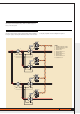
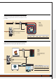
Confi guration and connection of the 2-relay actuator to control a zone pump
(in zone 7). The progressive number in the zone is 1. As relay RL2 is not used
it is excluded.
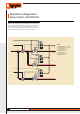
EXAMPLE
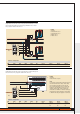
Example: configuration and connection of the 2-relay actuator to control two
circulation pumps (zone 00). The progressive numbers in the zone are 1 and 2.
LEGEND
1 actuator
2 check valve
3 pump zone 7
4 radiant panel
Actuator confi guration
[ZA] [ZB1] [N1] [ZB2] [N2] RL1/C1 RL2/C2
0 7 1 OFF – ON/OFF Excluded
LEGEND
1 actuator
2 boiler
3 chiller
4 heating circulation pump
5 cooling circulation pump
6 radiator
7 fan-coil
NOT CONNECTED
Raffrescamento
ART.F430/2
1
2
34
C1 C2
1234
C1
C2
N
L
BUS
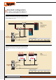
HEATING
4
1
3
5
2
7
6
Actuator confi guration
[ZA] [ZB1] [N1] [ZB2] [N2] RL1/C1 RL2/C2
0 0 1 0 2 Pump Pump
1 2
4
BUS
1
3
2
COOLING
35
TECHNICAL FEATURES
CATALOGUE MY HOME TEMPERATURE CONTROL