
Installation manual


Standard confi guration
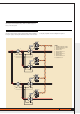
4-relay actuator item F430/4
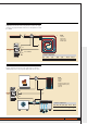
EXAMPLE
Confi guration and connection of two 4-relay actuators (one for cooling and
one for heating) to control a three-speed 4-tube fan-coil. For both actuators
the zone is 28. The progressive number for the actuator intended for the
cooling is 5, while for the actuator intended for the heating it is 6.
Contact C1 of each actuator commands the solenoid valve which is selected
fan
by the temperature control function depending on the system setting
(summer or winter). Contacts C2, C3 and C4 of the two actuators must
be connected in parallel to control the switching on and the speed of the
ventilation electric motor.
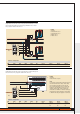
Heating actuator confi guration
[ZA] [ZB1] [ZB2] [ZB3] [ZB4] [N] RL1/C1 RL2/C2 RL3/C3 RL4/C4
2 8 8 8 8 6 Valve Minimum Average Maximum
speed speed speed
fan fan fan
Cooling actuator confi guration
[ZA] [ZB1] [ZB2] [ZB3] [ZB4] [N] RL1/C1 RL2/C2 RL3/C3 RL4/C4
2 8 8 8 8 5 Valve Minimum Average Maximum
speed speed speed
fan fan fan
M
NL
ART.F430/4
1
2
5
34
C1 C2 C3 C4
1
23
4 5
C1
C2
C3
C4
ART.F430/4
1
2
5
34
C1 C2 C3 C4
1
23
4 5
C1
C2
C3
C4
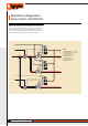
RISCALDAMENTO
4
1
3
5
2
BUS
BUS
SOLENOID VALVE
MIN. SPEED
AV. SPEED
MAX SPEED
SOLENOID VALVE
MIN. SPEED
AV. SPEED
MAX SPEED
LEGEND
1 chiller
2 boiler
3 cooling actuator
4 heating actuator
5 4-tube fan coil
Cooling
HEATING
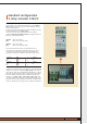
NOTE
If a fan-coil is used in heating systems the fan must
not turn when the water is cold, to avoid cooling
the room instead of heating it. Some fan-coils
have a water temperature sensor to perform this
function. If a fan-coil without sensor is used an
efficient solution is that of using an immersion
thermostat to be installed on the water return tube.
The thermostat contact commands a remote switch
to which the fan-coil power supplies are connected.
40
MY HOME TEMPERATURE CONTROL