
Installation manual


EXTENSIVE SYSTEMS
In large systems or systems which have current absorption greater than the
limit of 1200 mA supplied by the power supply item E46ADCN, the system must
be divided into several sections each supplied with its own power supply and
connected by means of interface item F422 confi gured in “physical expansion”
mode. It must be shown that the system limits, in terms of absorption and
maximum wiring distance, as shown in this guide, are applied for each bus. A
system made up of two or more buses, connected by interfaces confi gured in
“physical expansion” mode, cannot therefore be supplied with just one power
supply item E46ADCN, even if the number and types of component connected to
the system would not involve exceeding the maximum expected absorption (1200
mA). To produce the “physical expansion” mode interface item F422 must be
confi gured by inserting numerical confi gurator 1 in the MOD position. Positions 13
and 14 of the interface must be confi gured as a function of the two modes of use
of the interface itself as indicated below:
a. If a bus system with only Temperature control devices must be extended,
positions 13 and 14 of the interface must be confi gured with addresses 13 =
1 – 9 and 14 = 1 – 9 completely independent from the Temperature control
device addresses;
General installation
rules
b. If a bus system with Automation and Temperature control devices must
be extended, positions 13 and 14 must be confi gured as a function of the
confi guration of the Automation devices in the two connected systems.
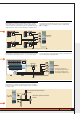
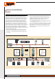
Referring to the illustration, let us suppose that 13 = 3, 14 = 2:
• on the input bus (IN) the Automation device addresses must be between
A = 1 / PL = 1 and A = 3 / PL = 1;
• on the output bus (OUT) the addresses must be between A = 3 / PL = 3 and
A = 9 / PL = 9 or the address of the next interface. It should be stressed that
all the Temperature control devices on the system section must be confi gured
totally independently of the Automation device confi guration. In any case
no automation device must be confi gured with the same address (A, PL) as
interface F422 (13, 14).
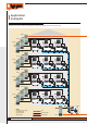
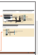
SYSTEM EXAMPLE
I1 = -
I2 = -
I3 = 3
I4 = 2
MOD = 1
OUT
IN
I1 = -
I2 = -
I3 = 5
I4 = 4
MOD = 1
A/PL = 11 31 A/PL = 55 99
1 3
A/PL = 33 53
2
60
MY HOME TEMPERATURE CONTROL