Operation Manual Rotavapor® Rä250 096796 en
Rotavapor R-250 Table of Contents Table of Contents 1 Scope of Delivery 2 2 Safety 3 3 Function 6 4 4.1 4.2 4.3 4.4 4.5 4.6 4.7 4.8 4.9 4.10 4.11 4.12 4.13 4.14 4.15 4.
Rotavapor R-250 1 Scope of Delivery 1 Scope of Delivery Component 1 Chassis, complete, with Control Rotation drive Heating bath, complete 1 Glass assembly, comprising 20 or 50 ltr. evaporating flask Condensation assembly Receiving assembly Table 1: Scope of delivery Standard accessories, comprising Ordering No. 1 Wrench 1 Hoses, complete 1 Installation tool 1 Instruction Manual German 96795 English 96796 French 96797 Italian 96798 Spanish 96799 1 Documentation CD 97XXX Table 2: Standard accessories Fig.
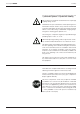
Rotavapor R-250 2 Safety 2 Safety This unit has been built in accordance with the latest state of the art and with recognized rules of safety. Nevertheless there are certain risks and dangers entailed with this unit: s WHENEVER THE UNIT IS OPERATED BY INDIVIDUALS WHO LACK sufficient training; s WHENEVER THE UNIT IS USED FOR SOME PURPOSE OTHER THAN its authorized use. 2.1 Symbols Stop Information on dangers that can cause serious material damage and severe personal injuries or death.
Rotavapor R-250 2 Safety 2.4 Unauthorized Use Any use other than those indicated above, and any use that is not in conformity with the Technical Data is considered to be misuse. The operator himself bears sole responsibility for all damage or injuries arising from any such use. The following applications in particular are strictly forbidden: s 4HE PRODUCTION AND PROCESSING OF MATERIALS THAT CAN cause spontaneous reactions, e.g.
Rotavapor R-250 2 Safety It is always mandatory to wear personal protective gear such as protective eyewear and protective clothing. The machine must never be rotated without the snap flange coupling being closed. No distillation may be started unless the evaporating flask is immersed in the bath. There is always the risk that the neck of the flask might break off due to the great weight involved. There is a risk of becoming scalded while changing evaporating flasks. Wearing gloves prevents this.
Rotavapor R-250 3 Function 3 Function A vacuum rotary evaporator is used for quick single-stage distillations that treat the product gently. The process is based on the evaporation and condensation of solvents in a rotating evaporating flask. It is possible to work under a vacuum to ensure gentler treatment of the product and increase productive output. Distillation may be done either under a vacuum or at atmospheric pressure. A secure tightness is only guaranteed in the low pressure range.
Rotavapor R-250 4 Putting into Operation 4 Putting into Operation The danger zone around the Rotavapor R-250 can extend outward by up to 10 m. When working inside this danger zone, there is a risk of damaging the glass parts, which could cause them to implode. 4.1 Installation Location Always set the unit up on a clean, stable, and flat surface. Never at a location where there is a great deal of personal traffic (breaking or broken glass) ! The ambient temperature must be between 5° and 40°C.
Rotavapor R-250 4 Putting into Operation 4.3 Connecting to the Source of Energy The rotary evaporator may only be connected to the electrical supply by the trained person who has been assigned responsibility for this task. The cooling medium must not exceed the maximum operating pressure of 1.7 bar (shock-free). 4.4 Setting Up the Support Rod s 0LACE THE SUPPORT ROD 햲 into the holders provided 햳, 햴 and fix it tight using the locking screw.
Rotavapor R-250 4 Putting into Operation 4.5 Attachement and Removal of the EasyClamp Connection Attachment of the EasyClamp s #AREFULLY LAY THE %ASY#LAMP AROUND THE GLASS AND FOLD the top and bottom segments together, closing them at their open connection point. s )NSERT THE BOLT THAT DOES NOT HAVE A SPACER SPRING AND tighten the knurled nuts slightly.
Rotavapor R-250 4 Putting into Operation 4.6 Installation of the Receiving Glass Assembly All glassware used must be intact, with no signs of cracks, spreading impact marks, or other damage. Inspect the glassware visually before installing it. Single receiver 햷 s )NSERT THE SUPPORTING RING 햲 into the connecting fitting 햳. s 3ECURE THE OUTLET VALVE 햴 to the flask 햵 using a DN 25 EasyClamp connection. 햶 s #ONNECT THE BRANCHING PIECE 햶 to the flask 햵. 햵 s )NSERT THE SHUT OFF TAP 햷 and tighten it firmly.
Rotavapor R-250 4 Putting into Operation 4.7 Installation of the Reflux Glass Assembly All glassware used must be intact, with no signs of cracks, spreading impact marks, or other damage. Inspect the glassware visually before installing it. s &IX THE REmUX DISTRIBUTION HEAD 햲 in position on the gear head using a DN 70 EasyClamp connection. 햳 s &IT THE COOLING WATER HOSE NIPPLES 햳 to both coolers 햴.
Rotavapor R-250 4 Putting into Operation 4.8 Installation of the Descending Glass Assembly All glassware used must be intact, with no signs of cracks, spreading impact marks, or other damage. Inspect the glassware visually before installing it. 햽 s &IX THE DESCENDING DISTRIBUTOR HEAD 햲 in position on the gear head using the DN 70 EasyClamp connection. 햺 s &IT THE COOLING WATER HOSE NIPPLES 햳 to the two or, if appropriate, three coolers 햴.
Rotavapor R-250 4 Putting into Operation 4.9 Attaching and Removing the Evaporating Flasks Attaching the flask s 7ITH THE SNAP mANGE COUPLING OPEN PLACE THE mASK IN position (by hand, using the manual flask handler or the crane). Fig. 4.8: Fitting the flask s #LOSE THE lRST SEGMENT OF THE SNAP mANGE COUPLING 4HE hook must latch in.) s #LOSE THE SECOND SEGMENT OF THE SNAP mANGE COUPLING using the closure screw that can be folded down to connect the two segments. Fig. 4.
Rotavapor R-250 4 Putting into Operation Removing the flask s 3LACKEN OFF THE CLOSURE SCREW USING THE HEXAGON WRENCH s 3UPPORT THE mASK BY HAND OR USING THE MANUAL mASK handler and then carefully lift up the closure screw. Fig. 4.11: Releasing the snap flange coupling s 0USH IN THE HOOK TO RELEASE THE SECOND SEGMENT AND FOLD it outwards. Fig. 4.12: Opening the snap flange coupling s ,IFT THE mASK OUT AT THE TOP AND REMOVE IT Fig. 4.
Rotavapor R-250 4 Putting into Operation 4.10 Operating the Shut-off tap 햳 햲 Fig. 4.14: Shut-off tap The shut-off tap is of a special design. It does not have a continuous thread on its inside for tightening it, but rather a sliding plane with two fixed latching positions. The closing pressure when it is in a closed position is provided by a prestressed spring.
Rotavapor R-250 4 Putting into Operation 4.12 Flask Suction (Optional) s ! MM DIA 04&% HOSE IS ROUTED FROM THE INSIDE THROUGH the SVL 15 threaded opening 햲 on the distributor head and the threaded connection is tightened. s 4HE HOSE IS THEN POSITIONED BY INSERTING IT INTO THE EVAPO rating flask. 햲 햳 Fig. 4.16: Flask suction (diagram) s ! 04&% ENCLOSED MAGNET 햳 is fitted to the front tip of the hose.
Rotavapor R-250 4 Putting into Operation 4.13 Vacuum Controller (Accessory) The process is carried out under vacuum to optimize evaporisation. The V-850/855 vacuum controller is most suitable for control. Installation of the vacuum controller s 3CREW THE SUPPORT 햲 onto the upper surface of the housing. s 3ECURE THE RETAINING ROD BY INSERTING THE SIDE SOCKET HEAD cap screws 햳 into the retainer.
Rotavapor R-250 4 Putting into Operation 4.14 Connections to the Vacuum and Cooling Medium Vacuum The Rotavapor R-250 is connected to the vacuum source on the rear panel. The vacuum hose is then routed from the venting valve (inside the unit) to the condensation unit. aeration valve For the reflux set-up both condensers are connected to the hose via a Y-piece. In the case of the descending glass assembly the vacuum hose is connected at the vacuum connector or at the third cooler. Fig. 4.
Rotavapor R-250 4 Putting into Operation 4.15 Heating Medium Never operate the heating bath when there is no heating medium in it! Suitable heating media include: s 7ATER SOME "ORAX SHOULD BE ADDED WHEN USING DEIOnized water). s (EAT TRANSFER OILS SUITABLE FOR USE AT TEMPERATURES UP TO 160° C (e.g., Ucon HTF 14, Fluka AG). s 7ATER SOLUBLE POLYETHYLENE GLYCOL (e.g., Polyethylene glycol 600, Fluka AG).
Rotavapor R-250 5 Operation 5 Operation Make sure that the unit has been commissioned properly as described in Chapter 4. 5.
Rotavapor R-250 5 Operation Adjusting the Optional Automatic Lowering of the Bath s 0RESS THE BUTTON h,)&4 DOWNv 햳, simultaneously switching on the main breaker switch 햲. 4HIS RESULTS IN THE DISPLAY h/.v OR h/&&v On = The lift lowering has been switched ON Off = The lift lowering has not been switched ON. s 4O SWITCH BACK AND FORTH BETWEEN /. AND /&& PRESS REPEATEDLY ON THE BUTTON h,)&4 DOWNv 햳.
Rotavapor R-250 5 Operation 5.4 Solvent Acetic acid Acetone n-Amyl alcohol, n-Pentanol Benzene Formula Molar Mass List of Solvents Evaporation Boiling Point Spec.Gravity Vacuum in mbar for a in g/mol Energy in J/g at 1013 mbar in g/cm3 Boiling Point at 40°C C2H4O2 C3H6O C5H12O 60.0 58.1 695 553 118 56 1.049 0.790 44 556 88.1 595 37 0.814 11 C6H6 78.1 548 80 0.877 236 n-Butanol, tert. Butanol C4H10O 74.1 620 118 0.810 25 (2-Methyl-2-Propanol) C4H10O 74.1 590 82 0.
Rotavapor R-250 5 Operation 5.
Rotavapor R-250 5 Operation 5.
Rotavapor R-250 6 Maintenance 6 Maintenance Please note all rules aimed at keeping the rotary evaporator in a functional condition. These also include periodic cleaning and inspection for any damage that might have occurred. Make certain that supply of power to the unit has been interrupted before doing any maintenance work on the unit. Always support the bath from below, on the underside of the bath whenever doing any repair work. 6.
Rotavapor R-250 6 Maintenance 6.2 Dismantling/Assembling the Flask Snap Flange Coupling Dismantling the snap flange coupling s #LOSE THE TWO SEGMENTS OF THE SNAP mANGE COUPLING s 4URN THE SNAP mANGE COUPLING BY ª UNTIL THE CLOSURE faces down. s (AVE 4OOL .O READY AT HAND s 2EOPEN THE CLOSURE s ,IFT THE st segment of the snap flange coupling to open it. s ,IFT THE nd segment of the snap flange coupling to open it. s 7ITH THREE lNGERS AT THE TIP REACH UNDER THE MIDDLE SEG ment and raise it up.
Rotavapor R-250 6 Maintenance 6.3 Removing/Inserting the Evaporating Flask Seal Removing the evaporating flask seal s 3EAL THE HOLDER FOR THE SEAL BY ª UNTIL THE OPENING faces up. s 4AKE HOLD OF THE SEAL WITH BOTH HANDS FROM ABOVE AND from the front, and pull it out slowly. s 4ILT THE SEAL SLIGHTLY AND CAREFULLY PULL IT ALL THE WAY OUT "E careful not to damage the glass centering bulge when doing so. s 2EMOVE THE VAPOR DUCT Fig. 6.
Rotavapor R-250 6 Maintenance 6.4 햲 Changing the Seals on the Distribution Head s /PEN THE $. %ASY#LAMP BY RELEASING THE KNURLED NUTS on all 3 bolts, but do not screw the nuts completely off. s 4ILT THE TOP BOLT OUT TOWARD THE BACK s /PEN THE UPPER AND LOWER %ASY#LAMP SEGMENTS AND carefully lift the distribution head off the glass assembly. s 4AKE OUT THE SEAL 햲 laid in at the front and replace it. Fig. 6.5: Replacing the seal in the distribution head 6.
Rotavapor R-250 6 Maintenance 6.6 Testing for Leaks With the assembled rotary evaporator in a clean and dry condition, test it to ensure that the vacuum system is free of leaks. To do this, evacuate the unit to below 100 mbar and then close the vacuum line. The rate of pressure rise must not exceed 3 to 5 mbar per 15 minutes. A greater pressure rise indicates a leakage. In such a case, recheck all EasyClamp connections and all valves. 6.
Rotavapor R-250 7 Taking out of Operation 7 Taking out of Operation Remove all hazardous materials and clean the unit thoroughly. This prevents any risk that individuals could suffer injuries due to contact with hazardous materials. 7.1 Storage Always store the unit and spare parts for it in a clean and dry location. 7.2 Packing / Transport The original packing has been specially designed for transporting the unit and the glass parts for it.
Rotavapor R-250 8 Spare Parts and Accessories 8 Spare Parts and Accessories Only original BÜCHI accessories and spare parts ensure safe operation and a proper functioning of the unit. The use of spare parts and accessories other than those from BÜCHI is permissible only with prior approval of the manufacturer. The Spare Parts Catalog may be used for purposes of assembly and disassembly only in conjunction with the corresponding Chapters 4 and 7 in this Operation Manual.
Rotavapor R-250 8 Spare Parts and Accessories 8.1 R 3577 / 5155 41436 27289 41155 41159 41151 41317 41131 41076 41336 41348 41130 27277 41338 Spare Parts, Glass Assemblies R, RB Component Threaded sleeve Svl 22 Seal Svl 22 Id 17 PTFE PTFE hose, Outer Diam. 10.0x1.
Rotavapor R-250 8 Spare Parts and Accessories 8.2 D 41076 41334 41151 41155 1165 27308 41131 1129 3577/ 5155 27277 41348 41436 41337 41335 41130 Spare Parts, Glass Assemblies D, D3 Component Vacuum connector PLG Expansion vessel PLG Threaded sleeve Svl 22 Seal Svl 22 Id 17 PTFE PTFE hose, Outer Diam. 10.0x1.
Rotavapor R-250 8 Spare Parts and Accessories 8.3 Spare Parts, Drip Tray Component 41318 41475 41130 41480 41446 41353 41405 41048 41318 41130 41480 41405 Fig. 8.3: Spare Parts: Drip tray 36 41445 41446 41353 Ordering No. Single receiver EasyClamp, DN25 Industrial tap, small Spindle support Angle seat valve, special Receiving flask 20 lt.
Rotavapor R-250 8 Spare Parts and Accessories 8.4 41094 Seals, Tools 41095 27378 41121 41084 20075 41229 41135 41230 41231 Fig. 8.4: Sealing elements Component 41346 41354 03223 00398 41147 41946 03549 Fig. 8.5: Inlet valve, complete Sealing elements Support ring inlet valve Seal SVL 30 Screw Cap SVL 30 Screw Cap SVL 15 Seal tool O-ring 130x5.0 Fpm70 Vapor duct Seal holder Vacuum seal Evaporating flask seal, complete EasyClamp element, DN70 Set of 5 O-rings 64x5.
Rotavapor R-250 8 Spare Parts and Accessories Component Fig. 8.6: Snap flange coupling complete with tool 41412 Ordering No. Snap flange coupling, complete Screw cap Tool 41415 41416 41472 Cooling water tap, complete .IPPLE h X MM .IPPLE h X MM 2EDUCER h X h 03693 03810 41412 41448 41448 03810 03696 Fig. 8.7: Cooling water tap, complete Cover for evaporating flask Material: PP Cover for evaporating flask D 150 mm Fig: 8.
Rotavapor R-250 8 Spare Parts and Accessories 8.5 Accessories Component Ordering No. Kolben Evaporating flask 20 ltr. Evaporating flask 50 ltr. 41432 41339 Drying flask 20 ltr. Drying flask 50 ltr. 41393 41394 This special flask is particularly suited for drying powdery substances or a homogeneous mixture of solid products. The baffles attached on the circumference of the flask ensure an intensive circulation of the contents inside the flask. Fig. 8.9: Flasks Splash protection Splash protection (cpl.
Rotavapor R-250 8 Spare Parts and Accessories Component Ordering No. Vacuum Controller V-850 for R-250 100 V - 230 V 47293 V-855 for R-250 100 V - 230 V 47292 Support Rod Communications cable (included in set) 41465 41426 40758 Fig. 8.11: Vacuum controller incl. support Water valve An additional water valve can be used to switch the cooling water. Water valve, complete Valve body Fig. 8.
Rotavapor R-250 8 Spare Parts and Accessories 8.6 Hose Connections Component Ordering No. Water: PVC hose, ID 10 mm PVC hose, ID 14 mm 27146 17383 Y-piece, 12 mm / 16 mm 41473 Pressure side (upstream of reduction valve) Softaflex, ID 8 mm Softaflex, ID 19 mm 04113 37617 Vacuum: Spiralflex hose, ID 16 mm 41441 Y-piece, Outer Diam. 16 mm T-reducer, 16 / 8 mm 41449 41474 Product: PTFE hose, Outer Diam.
Rotavapor R-250 8 Spare Parts and Accessories 8.7 Connections to Rear Panel 햴 햲 햵 햳 Fig. 8.13: Connections to rear panel Component Ordering No.
Rotavapor R-250 R-250 Power connection Connection voltage Fuse (live, neutral) Site condition Evaporator output Rotation drive Speed control Bath output Bath dimensions Bath pan Bath heater control Bath temperature range Overheating protection Bath lift Battery Measurement of vapor temperature Displays Aeration Installation category Degree of pollution Cooling area Vacuum pump Cooling water consumption Weight Dimensions 9 Appendix 9 Appendix 9.1 Technical Data 7.
Rotavapor R-250 9 Appendix 9.
BÜCHI Labortechnik AG CH-9230 Flawil 1 / Switzerland T +41 71 394 63 63 F +41 71 394 65 65 www.buchi.