Operation Manual SpeedDigester K�439 11593351 en
Table of contents Table of contents 1 2 3 4 5 6 3 About this manual . . . . . . . . . . . . . . . . . . . . . . . . . . . . . . . . . . . . . . . 5 Safety . . . . . . . . . . . . . . . . . . . . . . . . . . . . . . . . . . . . . . . . . . . . . . 6 2.1 User qualification . . . . . . . . . . . . . . . . . . . . . . . . . . . . . . . . . . . . 6 2.2 Proper use . . . . . . . .
Table of contents 7 8 9 10 11 4 6.7.1 Kjeldahl digestion —preparing sample tubes . . . . . . . . . . . . . . . . . . . . . . 37 6.7.2 Peroxide digestion —preparing sample tubes . . . . . . . . . . . . . . . . . . . . . . 38 6.7.3 Installing a suction module and sample tubes (300 ml) . . . . . . . . . . . . . . . . . 39 6.7.4 Installing 500 ml sample tubes . . . . . . . . . . . . . . . . . . . . . . . . . . . . .
1 1 About this manual About this manual This manual describes the SpeedDigester K-439 and provides all information required for its safe operation and to maintain it in good working order. It is addressed to laboratory personnel and operators in particular. Read this manual carefully before installing and running your system and note the safety precautions in chapter 2 in particular. Store the manual in the immediate vicinity of the instrument, so that it can be consulted at any time.
2 2 Safety Safety This chapter introduces the safety concept of the instrument and contains general rules of behavior and warnings from direct and indirect hazards concerning the use of the product. For the users safety, all safety instructions and safety messages in the individual chapters shall be strictly observed and followed. Therefore, the manual must always be available to all persons performing any tasks described herein. 2.
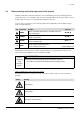
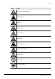
2 2.4 Safety Safety warnings and safety signs used in this manual DANGER, WARNING, CAUTION and NOTICE are standardized signal words for identifying levels of hazard seriousness of risks related to personal injury and property damage. All signal words, which are related to personal injury are accompanied by the general safety sign.
2 Symbol Safety Meaning Explosive gases, explosive environment Explosive material Fire hazard Harmful to life-forms Hot item, hot surface Device damage Inhalation of substances Chemical burns by corrosives Fragile components Wear laboratory coat Wear protective goggles 8 K-439 Operation Manual, Version A
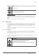
2 Symbol Safety Meaning Wear protective gloves Heavy weight, lifting requires more than one person Additional user information Paragraphs starting with Note transport helpful information for working with the device / software or its supplementaries. Notes are not related to any kind of hazard or damage (see following example). Note Useful tips for the easy operation of the instrument / software. 2.
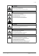
2 ! Safety WARNING Death or serious burns by flammable vapors. • • Remove all sources of flammable vapors Do not store flammable chemicals in the vicinity of the device ! WARNING Risk of death or serious chemical burns by hot acid or peroxide fumes.
2 2.5.2 Safety Warning labels on housing and assemblies The following warning sticker(s) can be found on the housing or assemblies of the SpeedDigester: Symbol 2.5.3 Meaning Location Hot item, hot surface Sticker / label, located on top of the housing and at the racks Do NOT put rack into side cooling position Label on 500 ml racks Personal protective equipment Always wear personal protective equipment such as protective eye goggles, protective clothing and gloves.
2 2.5.4 Safety Built-in safety elements and measures Buchi glassware design • A ll original Buchi digestion glassparts are made of high temperature and chemical resistant borosilicate glass. • Acid fumes generated during digestion accumulate in the suction module • The fumes must be safely withdrawn from the suction module via one or more hoses to a Scrubber (e.g. Scrubber B-414) or via water jet pump into a sink or sufficient suction flow.
3 3 Technical data Technical data This chapter introduces the reader to the SpeedDigester K-439 and its specifications. It contains the scope of delivery, technical data, requirements and performance data. 3.1 Scope of application and delivery All system configurations come with a limited set of accessories as a starter kit. Within a system family, additionally available accessories (see section 3.1.
3 3.1.2 3.1.3 Technical data Accessories for 300 ml sample tubes (for standard applications) Item Additional info Order number Recommended quantity to order Set of sample tubes 300 ml, 4 tubes 037377 3x Suction module standard 6 place 11055849 2x Suction module condensate trap 6 place 11055865 2x Suction module H2O2 6 place, cpl.
3 3.1.4 Technical data Accessories for 3rd party production, 250 ml sample tubes Item Additional info Order number Recommended quantity to order 3rd party sample tubes 250 ml n.a.
3 3.2 Technical data Technical data The table below lists all main design parameters of the SpeedDigester K-439. Technical data Power consumption max. 2000 W Temperature control range 50 – 580°C Temperature accuracy ± 5 K at 200 °C / ± 10 K at 550 °C Connection voltage 220 – 240 VAC Frequency 50 / 60 Hz Input fuse T 10A L 250 V Scrubber output max.
3 3.
4 4 Description of function Description of function This chapter explains the basic working principle of the SpeedDigester K-439. It also shows how the instrument is structured and provides a general functional description of its assemblies. 4.1 Functional principle The SpeedDigester K-439 is a special heating device to digest samples. It can generate max. temperatures of 580 °C. This allows e.g.
5 5 Putting into operation Putting into operation This chapter describes how the instrument has to be installed. It also gives instructions for the initial startup. Note Inspect the instrument for damage during unpacking. If necessary, prepare a status report immediately to inform your Buchi representative. In some countries it is necessary to additionally inform the postal company, railway company or transportation company. Keep the original packaging for future transportation. 5.
5 ! Putting into operation WARNING Risk of death or burns by electric current. • • Check for proper grounding before use Exchange defective cabling instantly ! CAUTION Risk of minor or moderate injury by heavy weight of the instrument. • • • • 5.
5 5.3 Electrical connections 5.3.1 SpeedDigester connection Putting into operation After the installation procedure has been completed successfully, the power plug of the SpeedDigester must be connected to the mains for the digestion process. Notice Risk of instrument damage by wrong mains supply. • • External mains supply must meet the voltage given on the type plate Check for proper grounding The used mains circuit has to: • provide the voltage that is given on the type plate of the instrument.
6 6 Operation Operation This chapter gives examples of typical instrument applications and instructions on how to operate the instrument properly and safely. See also section 2.5 “Product safety” for general warnings. 6.1 Operating controls and housing The SpeedDigester K-439 is equipped with electronic temperature control, an integrated LC-display and a membrane keypad with multifunctional keys. Up to 50 methods can be programmed, 20 of which are already predefined by default.
6 6.1.2 Operation System rear side Bracket with magnetic (elbow) suction plugs T-piece with suction hoses Type plate Mains socket for Scrubber connection Power socket Fuse holders Fuse type: T 10A L 250 V • 23 To access the glass fuses on the rear side use a slotted screwdriver. ➥ Slightly push in the slotted insert and turn it approx. a quarter-turn counterclockwise. ➥ Release the pressure off the insert — it will pop out by weak spring force.
6 6.
6 6.
6 6.
6 6.5 Operation Software icons The software icons explained in the following are visible during a digestion process. Most of them are displayed in the upper part of the software screen and also remain visible when leaving the digestion screen. Just the general icon for the selected rows and the temperature reached as well as the heating icons in the manual mode are only visible in the digestion screen. 6.5.
6 6.6 Operation How to prepare the software for routine digestion Configure the software according to the following steps to prepare it for routine digestion: 1. Standard instrument settings 2. Manual mode (development of digestion method) 3. Digestion methods (storage of developed method) 4. Preheating 5. Start digestion 6.6.1 Standard instrument settings This configuration consists of typical settings, which have to be defined before the instrument is used for the first time.
6 6.6.2 Operation Digestion in Manual Mode The manual digestion mode is mainly used for the development of new digestion methods. The temperature is set manually and can be changed at any time. The total runtime of the digestion is displayed and can be reset. Select Main Menu > Manual. The following dialog appears: • Set the required temperature by using the ± buttons. • Select the row(s) to be active, by pressing Row and then the ± buttons. Then press OK to confirm. • Now press START.
6 6.6.3 Operation Methods menu The software of the SpeedDigester K-439 provides 20 predefined Buchi methods, which can be used for immediate digestion and as a basis for method development. Their names are always written in lower case letters. They cannot be deleted but modified and stored under a new name. When customer methods are available, the Buchi methods are always listed behind them. Buchi methods The following Buchi methods are available, e.g.
6 Operation Defining/Editing a method It is possible to enter 30 user specific methods. For this purpose an existing Buchi method can be modified and saved under a new method name. • Select Main Menu > Methods. • Highlight the method that should be edited by using the up or down buttons. • Press >> and afterwards >. • Now press Edit. • Select the temperature for preheating, time and temperature for the 4 possible digestion steps and the cooling down time using the ± buttons.
6 Operation Note If the rack(s) is/are cooled down inside the heating chamber, the time for the cool down step in the corresponding method must be set to ≥ 80 min, so that no harmful vapors can escape. If the racks are cooled outside the heating chamber, the cool down step in the corresponding method must be set to ≥ 30 min. • Press Save. • Now enter a name for the new method by highlighting individual letters on the virtual keyboard with the ± buttons and press Enter to confirm a letter.
6 Operation Deleting a method The 20 Buchi standard methods predefined in the instruments software cannot be deleted. A customer specific method can be deleted as follows: • Select Main Menu > Methods. • Highlight the method that should be deleted by using the up or down buttons. • Press >>. • Now press Delete. The following message appears: • Press Yes to confirm. The selected method is now deleted.
6 Operation Starting an automatic digestion by loading a method • Select Main Menu > Methods. • Highlight the method that should be loaded by using the up or down buttons. • Press >>. • Now press Load. The “Automatic” screen appears. • Select the row(s) to be active, by pressing Row and then the ± buttons. Then press OK to confirm. • To define an optional delay time for the start of the digestion, press Timer and enter the corresponding time (in hh:mm) using the ± buttons. Then press OK to confirm.
6 Operation All entered steps are now run through automatically. The set and actual temperature as well as the remaining time, which includes the entered cooling-down time, are indicated on the display • As soon as the heating process is finished, the display starts blinking, the buzzer beeps and the info message "Heating finished" appears. Confirm the message by pressing OK. The racks now have to cool down.
6 6.6.5 Operation History menu The data of the last three digestions can be viewed/checked within the History menu For this purpose select Main Menu > History. The History screen appears. You can now navigate through the available digestion data using the Prev or Next button. To view the set and actual temperature of a certain time within the digestion process use the ± buttons to move forward or backward on the progressive diagram. 6.
6 ! Operation WARNING Death or serious poisoning by contact or incorporation of harmful substances at use.
6 6.7.2 Operation Peroxide digestion —preparing sample tubes During the preparation process, handling with peroxides and other dangerous substances is inevitable. Peroxides are strong oxidants and can form explosives! All steps must be performed under safe laboratory conditions. ! WARNING Death or serious injuries by toxic and explosive peroxides.
6 6.7.3 Operation Installing a suction module and sample tubes (300 ml) To withdraw hazardous fumes and vapors a suction module must be installed. Prerequisites: All hoses and connectors must be unclogged. Installation steps: For installation and handling all parts must be < 40 °C! • • • Install the plastic adapter piece to the suction module 1. Mount the hose connector at the EPDM hose 2 of the suction module (i.e. Scrubber B-414 or water jet pump).
6 Operation Note • Make sure the adapter piece is tightened well without damaging the glassware. • Keep suction hose(s) as short as possible under the given circumstances. • Unused positions should be arranged at the rear end of the rack. 4 3 3 Rear side • • Lift the metal clips to unlock and shift the black handles 3 aside. Carefully push down the suction module 4 straight onto the sample tubes and shift the handles back into locking position.
6 • • Operation If applicable, follow the previous steps to install a suction module on a second rack. Switch on the Scrubber or water jet pump and activate the fume hood ventilation. ➡The rack(s) can now safely be processed in the SpeedDigester. Note • Clean all glass parts before mounting to avoid cross contamination. • When a water jet pump is used, hazardous vapours can escape into the environmental air if the suction is inadequate.
6 • • • Operation Insert the prepared sample tubes into the rack(s) 2— start with the first (front) position. Install the rake 3 to interlock the sample tubes at their head side. Check for secure interlocking! To separate the rack from the carrier, pull the unlock buttons 4 on both sides of the rack and lift it off the carrier. ! WARNING Risk of death or serious chemical burns by acids or peroxides when rack tilts.
6 6.7.5 Operation Starting up the SpeedDigester System preconditions The system must be correctly installed and fully functional. All parts must be in proper condition (e.g. clean and free of damage). See also section 2.5 “Product safety” for general warnings! Start-up procedure • • • • • • • Select and install insulation plate(s) according to the type of sample tubes. Install insulation caps at unused positions of the insulation plate(s) for 300 / 500 ml racks.
6 Operation ➥ Depending on the sample material and acid / catalyst composition it might be necessary to vary the digestion temperature at different time intervals (digestion method). 6. A t the end of an Automatic digestion confirm the corresponding info message "Digestion done" by pressing OK. At the end of a Manual digestion press Stop to finish the process, then switch off the instrument via the mains switch. ➡ The samples are now digested. Follow-up actions are described in section 6.10. 6.
6 Operation ➡ The samples are now digested. Follow-up actions are described in section 6.10. ! DANGER Risk of death or serious injuries by toxic and explosive peroxides.
6 6.10 Operation Finishing a digestion process ! WARNING Risk of dangerous or moderate burns when handling hot parts and sample tubes.
6 Operation Cooling positions of SpeedDigester K-439 The side position shown in the drawing below is only applicable for 300 ml and 250 ml sample tubes and racks. Due to the larger diameter of 500 ml sample tubes the glassware does not fit between rack and housing. Racks with 500 ml sample tubes must not be installed in this position (see illustration)! 300/250 ml rack in side position (DO NOT USE THIS POSITION FOR 500 ml RACKS / TUBES) Note • A color change takes place during the cooling.
6 ! Do NOT use the side positions with 500 ml rack / glasses! Operation ! 500 ml racks must be placed beside the SpeedDigester K-439 to avoid a crash between the sample tubes and the housing. Nonobservance will lead to hazardous situations especially when the sample tubes are filled and hot! ! WARNING Death or serious injuries at glass breakage by hot acid and catalyst or peroxide.
6 6.11 Operation Optional 'Stand with drip tray' The optional accessory drip tray serves to collect condensated acid which might drip off the suction module(s) after a digestion process and as a space saving way to securely store a suction module. Stand with drip tray (illustration with suction unit) Screw and holder-knob Installing a drip tray 1. Screw the two holder-knobs into the designated threads at the side of your SpeedDigester. 2. Hook-in the frame of the drip tray.
7 7 Maintenance and repairs Maintenance and repairs This chapter gives instructions on maintenance work to be performed in order to keep the instrument in a good and safe working condition. All maintenance and repair work requiring the opening or removal of the instrument housing must be carried out by trained service personnel and only with the tools provided for this purpose.
7 Maintenance and repairs NOTICE Risk of housing and instrument damage by liquids and detergents. • • • 7.1 Do not spill liquids over the instrument or parts of it Wipe off any liquids instantly Use ethanol or soapy water as detergent only Customer service Only authorized service personnel are allowed to perform repair work on the instrument. Authorization requires a comprehensive technical training and knowledge of possible dangers which might arise when working at the instrument.
7 7.2.1 Maintenance and repairs Breakage of glassware inside a housing chamber Under rare conditions charged sample tubes or other glassware might break inside a housing chamber. In such a case strictly follow the cleaning instructions below! Cleaning under safe conditions • • • • • • • • Switch off the SpeedDigester and unplug the power cord. Let the system and the rack(s) cool down completely! Carefully remove the installed rack(s). Wear safety gloves to dispose of the defective glassware of the rack.
7 7.3 Maintenance and repairs Glass component conditions Clean the glass components after each working process to prolong their lifetime. The glass assemblies can be taken out and cleaned manually with water and a commercial cleaning agent (e.g. mild soap solution) or in an ultrasonic bath. Visibly check for damages at all the glass components subsequently. Note • It is recommended to clean all glass components in use.
7 Maintenance and repairs the possibility of unwanted sample contamination (foaming or boiling retardation). Afterwards dry the cleaned seals with a soft cloth. 7.5 Rack system To prolong the lifetime of the racks, rinse them with water thoroughly to remove possible acid residues. Subsequently, clean the racks with non-abrasive cleaning agents (e.g. soapy water). 7.5.1 300 ml sample tube support spring The 300 ml tube rack is equipped with six sample tube support assemblies.
7 7.5.2 Maintenance and repairs 500 ml sample tube support spring The 500 ml tube rack is equipped with a tube holder containing five sample tube support springs. Each flat spring must be freely rotatable by a small amount. If swivelling is not possible, exchange the rake! Note • Rinse the tube holder with water after use to avoid corrosion. • Store it dry and clean after use. 7.6 Display cover The display cover is equipped with double-faced adhesive tape.
8 8 Troubleshooting Troubleshooting This chapter helps to resume operation after a problem has occurred with the instrument which does not require special technical training. It lists possible occurrences, their probable cause and suggests how to remedy the problem. The troubleshooting table below lists possible malfunctions and errors of the instrument. The operator is enabled to correct some of those problems or errors by him/herself.
8 Troubleshooting Malfunctions and their remedy Malfunction Possible cause Remedy System does not heat No voltage Insert mains plug, examine plug for damage, check power switch Mains switch is turned off Switch must light up green, when system is powered up Fuse has been activated Exchange fuse(s), see section 8.
6 8.2.2 Operation Sensors This submenu enables the user to check the functionality of the following sensors: • • • • • 8.2.3 Voltage: xx VAC Triac temp.: xx °C LCD temp.: xx °C Temperature sensor 1: xx °C Temperature sensor 2: xx °C Operating Hours This submenu enables the user to view the operating hours of: • • • • 8.2.4 Power-on Time: xx h Heating Time: xx h Row Left: xx h Row Right: xx h Unit Information This submenu indicates some unit information: • • • • • 8.2.
6 8.3 Operation Device fuses To change a defective fuse proceed as follows • • • • Switch off the SpeedDigester and unplug the power cord. To access the glass fuses on the rear side use a flat screwdriver blade. ➥ Turn it approx. 5 turns anticlockwise to free the insert. ➥ Take out the insert together with the fuse. Replace the defective fuse (see technical data for fuse type!) Reconnect the SpeedDigester to the mains. ! WARNING Death or serious burns by electric current.
9 9 Shutdown, storage, transport and disposal Shutdown, storage, transport and disposal This chapter instructs how to shut down and to pack the instrument for storage or transport. Specifications for storage and shipping conditions can also be found listed here. 9.1 Storage and transport Switch off the instrument and remove the power cord. To disassemble the SpeedDigester K-439 follow the installation instructions in section 5 in reverse order.
9 9.2 Shutdown, storage, transport and disposal Disposal For instrument disposal in an environmentally friendly manner, a list of materials is given in chapter 3.3. This helps to ensure that the components can be separated and recycled correctly by a specialist for disposal. For disposal of liquids and consumables such as catalyst or acid, see data sheets of these chemicals! You have to follow valid regional and local laws concerning disposal.
9 Shutdown, storage, transport and disposal Health and Safety Clearance Declaration concerning safety, potential hazards and safe disposal of waste. For the safety and health of our staff, laws and regulations regarding the handling of dangerous goods, occupational health and safety regulations, safety at work laws and regulations regarding safe disposal of waste (e.g.
10 10 Spare parts Spare parts This chapter lists spare parts, accessories and options including their ordering information. Only order spare parts and consumables from Buchi to maintain the warranty status and to assure best performance and reliability of the system and affected components. Any modifications to the spare parts used are only allowed with the prior written permission of the manufacturer.
10 Spare parts Optional parts 64 Description Order no.
10 Spare parts Optional parts Description Order no. Stand with drip tray 11055216 Digestion rod (set of 10) 043087 Consumables 65 Description Order no. Kjeldahl tablets (Hg / Se-free), 250 pcs.
11 11 Declarations and requirements 11.1 FCC requirements (for USA and Canada) Declarations and requirements English: This equipment has been tested and found to comply with the limits for a Class A digital device, pursuant to both Part 15 of the FCC Rules and the radio interference regulations of the Canadian Department of Communications. These limits are designed to provide reasonable protection against harmful interference when the equipment is operated in a commercial environment.
11 11.
BÜCHI Labortechnik AG CH-9230 Flawil 1 / Switzerland T +41 71 394 63 63 F +41 71 394 65 65 www.buchi.