~~m!~ii unmatched biB ™ Your Energy Answer ™ INSTRUCTION FREESTANDING, MASONRY INSERT, AND BUCKMATE INSERT MODEL MODEL MODEL MODEL MODEL MODEL 26000-B STOVE 27000-B STOVE 28000 STOVE (Not UL Listed) ZC-2-01 UTILE BUCKMATE ZC-3-01 REGULAR BUCKMATE Fp·201 FIREPLACE Contact local building and/or fire officials about restrictions and installation inspection in your area.
TABLE OF CONTENTS INTRODUCTION BUCK STOVE FEATURES SECTION I SECTION II Inside Cover 2 MASONRY INSERT INSTALLATION MINIMUM CLEARANCES REQUIRED FIREPLACE DIMENSIONS TOOLS FOR INSTALLATION INSTALLATION PREPARATION POSITIONING THE BUCK STOVE MOUNTING THE TRIM PANELS SEALING THE TRIM PANELS FINAL STEP FINAL CHECK , , FREE·STANDING INSTALLATION MINIMUM CLEARANCES TOOLS FOR INSTALLATION INSTALLATION PREPARATION !' DETERMINING THE CHIMNEY LOCATION FINAL CHECK 4 5 6 6 7 7 7 11 11 12 13 14 23 23 24 25 , SECT
The BUCK STOVE Models 26000·B, 27000·B, and 28000 are safe and efficient heating systems which utilize either wood or Bituminous coal as fuel. The installation and operating instructions found in this manual have been developed through extensive laboratory testing and in the field experience. The procedures outlined MUST be followed exactly to ensure a safe and operational installation as well as to validate your war· ranty.
BUCK STOVE FEATURES Before attempting to install or operate your BUCK STOVE, It is a good idea to familiarize yourself with the features and operating controls of the stove. (Figure 1) OPERATING CONTROLS 1. DAMPER: The damper contrails located In the center of the stove, just under t he stove top. Ilis operated by lifting up on the control handle, and then pushing or pulling the handle. When the handle is lowered, the control locks Into position.
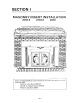
SECTION I MASONRY INSERT INSTALLATION 26000-B 27000- B V II 1 J( II U II II ~ ,~=--··,--_2 ---, .-- " II I I I I • II HI I I I I J II, I BI '11 .- n --~~/~. - I II I:t ~~~I I [ IE I I .. 1 61 • • • 1/ l~~ (~ - ~I fI{ I , .~, ~-_._--' \.;:::fuUnD G] rJ t. j - . Ie . I:::.~I II .. .,-' aJm1lllJ~ ; I II II IJ _ ... - ,J [0 ~ II L:f-I 11 ~ ~ ,,1 n.. II lIT Jl II ) .. ~ .. l.. .. VI L ....... 10 " '( r_~~ '7 I , , ,'.
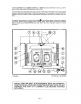
SECTION I: INSTALLATION A FIGURE 1 ALL DIMENSIONS SHOWN ARE MINIMUM ALLOWED FOR WARRANTY INSTALLED MINIMUM CLEARANCES Minimum Clearances: The BUCK STOVE fireplace Models 26000-B, 27000-8 and 28000 are intended for installation in accordance with the standard for chimneys, fireplaces, vents. and solid-fuel burning appliances, NFPA-211 code. BUCK STOVES are NOT intended for use with a factory-built metal fireplace. See Section III for Buck Stove/BuckMate Installation Instructions.
NOTE: Hearth Extension must be 38" wide )( ~" thick non·combustible inorganic material equal to ~ .. thick millboard having a thermal conductivity of K =0.84 BTU/P HO F inches Depth Dimension is determined by Depth of Masonry Hearth.
INSTALLATION PREPARATION Fireplace 1. Locate furniture and other materials away from the front of the fireplace to allow free access to the fireplace. 2. Cover the hearth and adjacent floor areas with the drop cloths to protect from soiling or marring the surfaces. 3. Remove the existing fireplace damper plate. 4. Thoroughly clean the fireplace of ashes and soot. 5. Check the chimney and smoke chamber for excessive bUildups of creosote or soot. Also, check fOf, obstructions, such as bird nest.
4. Mount the side trim panels. (See Figure 5) a. Position the trim panel on the reference line. b. Drill Mounting Holes in center of trim panels mounting brackets to allow for adjustment in and out If necessary. c. Mount the trim panel using the self·tapping screw provided. 5. Ends of gold trim should be prepared for easier insertion to touch stove top In side and top trim panels. (See Figure 4) 6. Mount top trim panel and Insert gold trim.
7. Set the top trim panel In place and mount the same as the side panels. 8. Slide the BUCK STOVE back Into the fireplace. Check to be sure that the trim panels are pro· perly positioned and lie flat against the front of the fireplace. If one or more of the panels is out of position, slide the stove out and reset by loosening the mounting screws and reposi· tloning in the slot. (See Figure 7) FIGURE 7 CHECKING TRIM PANEL ADJUSTMENT MINIMUM CLEARANCE FOR BUCK STOVE FIREPLACE INSERTS MODIFIED TRIM KIT.
BENDING MODIFICATION TIPS FOR MODIFIED TRIM KIT FLAT DEVELOPMENT \ \ ,-- , ;--. I I I I .' _ .J r --\.
SEALING THE TRIM PANELS Standard Caulking Gun It is necessary to seal trim panels against the stove and against the fireplace front. This will prevent the loss of warm room air up the chimney. 1. (See Figure 9) Using the caulking gun and a cartridge of RTV silicone, run a bead of silicone all the way around the inside of the trim panels next to the stove. 2. (See Figure 10) Attach 1 1/2" x 2" strip insulation around the back edge of the trim panels. Set the strip back 1" from the edge.
==:J c=::J c=J 1......-.-"-"----'-"-----'"'----»---- l -) c=:J c==J c=::J c=J .c=J r==J r===r FINISHED VIEW FIGURE 11 3. Install the firedogs (or coal grate, refter to Page 56), and replace the doors. Note: Model 28000 is standard with bottom refractory only. Rear and side refractory can be purchased separately and must be used when burning coal. FINAL CHECK 1. Recheck the specified clearances. 2. Remove all foreign material from the firebox area. 3. Open the primary air drafts and damper. 4.
SECTION II FREE-STANDING INSTALLATION 26000-8 27000-8 28000 SAFETY NOTICE If this stove is not properly Installed, a house fire may result. For your safety, follow the Installation directions. Contact local building or fire officials about restrictions and Installation Inspection requirements in your area. When a BUCK STOVE is to be installed as freestanding fireplace stove, kits No. L1 or P1 and S1 must be used.
SECTION If MINIMUM CLEARANCES The BUCK STOVE Models 26000-8 and 27000-B must be installed in compliance with the instructions contained in this manual. A NOTE: Oimonsion, Shown ."Minimum CI•• III Woll r.""" Clearance from combustible walls and ceilings. Combu..i:'", Wilt 16" flO()( ProtoctOt _ Minimum Sin Chart "A" The minimum lateral distance between any part of the BUCK STOVE models 26000-8 and 27000-B are shown in figures 1 and 2.
Reduced Clearances Using Wall Protectors (These are minimum clearances, minimal floor protection sizes and minimal wall protection sizes, Larger sizes and clearances are allowed.) 26000-8 LITTLE A. CORNER INSTALLATIONS 1. Using 3V2" masonry without ventilated air space. _._----"'Floor Protector T - 37"- 39" .......'------l---l-~J-.- L_ _ Finished Floor Line TOP VIEW FRONT VIEW 2, Using 3 112" masonry with 1" ventilated air space. Wall Protector Combustible Wall .......
26000-8 (Continued) 3. Using 24 gao sheet metal with 1" ventilated air space. Wall Protector Combustible Wall 531.. 1" From Celling 31" Floor Protector 43" I t" From Finished Floor J,-.~. ~d=====;;;;.;:i.;;;;::"-.L_ I'" 38" ----;1 .....-----50.. - - - - ..1 FRONT VIEW TOP VIEW B. PARALLEL WALL INSTALLATIONS 1, Using 3 112" masonry without ventilated air space, Combustible Wall Wall Protector -----.----ic::r==--;---- 1 32'35112" ..
26000·8 (Continued) 2. Using 3 W' masonry with 1" ventilated air space. HI 32 ITU 1" Air Space ~_.-' 1" Air Space _ 32" 1-4--35"--- ~ .:j 38'12 !.L.....-_ _ 1 - + - - - 44 1/B"'----JIoj ~::::J:::.-Crl=J::=:c.~ ~1'/ ~ry Skip other brick top and bottom to allow for air flow behind masonry Floor Protector FRONT VIEW TOP VIEW 3. Using 24 gao sheet metal with 1" ventilated air space.
27000·B BUCK STOVE A. CORNER INSTALLATIONS 1. Using 3 1/2" masonry without ventilated air space. Wall Protector Combustible Wall 1'----'1--'--' _ _'LLJ' 10lh" 'f 7" -'f'" " Floor Protector l 4'" Finished Floor line TOP VIEW FRONT VIEW 2. Using 3V2" masonry with 1" ventilated air space.
27000~B (Continued) 3. Using 24 gao sheet metal with 1" ventilated air space. Combu tibia Wall Wall Protector 1" From Ceiling 31'1... ~ 31" Floor Protector 5314' I '_+-- 41" 45" \1" From Fi,lished Floor 1" Air Space 1--- 41" ~--- -1 ---- ~===i:::::::i...- 53"-----1 FRONT VIEW TOP VIEW B. PARALLEL WALL INSTALLATIONS 1. Using 31/2" masonry without ventilated air space. Combustible Wall Wall Protector 1 u··.. 3 5"38"-" 471/2' '1 I o o t - - - - 51" - - - , .
27000-B (Continued) 2. Using 3 112" masonry with 1" ventilated air space. Combustible Wall Wall Protector 3'/2" TO< 45" 1" Air Space Ie 40V2'-'--to-i I... ....r . - - - - 44 "-------to{ 1-'4------ 49 5/8'-'------i~.._tl Floor Protector 1 - -- 1" Air Space Skip every othor brick tall and bOnOHl 10 iiii'JW for ar,c flow behind masonry FRONT VIEW TOP VIEW 3. Using 24 gao sheet metal with 1" ventilated air space. Combustible Wall Wall Protector --\----------------------f-------.:..
MASONRY CLEARANCE REDUCTION COMBUSTIBLE WALL ../'!( 1" Minimum air space between masonry and combustible wall. 4" nominal ~:jJ_---"''"4rll:;::;--- Corrugated metal wall ties brick wall ::':---R:ll'I::'~~ Skip every other brick bottom and __~~~~~~ top for ventilation A strip of heavy gage steel may be used for support------------~· ~ 1 (REF.• NFPA 211 CODE) Screw anchor (or nail) ....
MINIMUM CLEARANCES The BUCK STOVE Model 28000 The BUCK STOVE Model 28000 (NOT UL LISTED) must be installed in compliance with lhe instructions contained in this manual. ... NOTE: OH1,*o~n, Shown Wall .re Mfllimum CI.,,·",nc::1' to Comb.... ,,:>.. The minimum lateral distance between any part of the 28000 and a combustible wall is 36". (See Figures 3 & 4) w.1l )6" floot P,ot«Cla, ... M,n""...
CHIMNEY The BUCK STOVE Models 26000-B and 27000-B are designed for connection to either an 8" inside diameter Underwriters' laboratories, Inc. listed all-fuel residential type and Building Heating Appliance Chimney, or to a masonry chimney which meets the specifications of the National Fire Protection Association's 211 Code and has a minimum cross section area of 50 square inches (7 1/4" x 7 1/4" or 8" round). CAUTION: Use only U.l. Listed type HT chimney rated at 2100° F for freestanding installations.
8. Attach the stack by placing the stack brackets down on the lip on the Inside lower edge of the stack. Insert the bolts through the holes In the damper brackets and fasten securely with the lock washers and nuts provided. Be sure the stack sits squarely on the top of the stove with the gasket material making a good seal. (See Figure 6.) :.----Slack Clamp PREPARING THE BUCK STOVE LOCATION -~~ lo
Through-the-wall Penetration - ATTIC- Mark the plumb line on the wall directly behind the center of the stack (See Figure 8). Place the vertical position of the stove pipe and the elbow in position and project a point onto the plumb line level with the center of the elbow. Measure up so there will be at least 1/4" rise per foot of horizontal conneclor plpo, maintain c1earnaces to colling noted In Figure 8. This will give you the cenler of the hole for the chimney penetration. CElllNG 18"MIN.
6. Check for smoke leaks around the doors. 7. Open the doors and install the firescreen. Check for smoke escaping from the front of the stove. Smoking usually indicates a defective or poorly positioned chimney. If a thorough review of the installation instructions does not reveal the problem, contact your BUCK STOVE dealer for assistance. TIPS ON FIRE BURNING ASH BED - Prolongs burn and helps the thermostat function properly. For best result, the ash bed should be equal to the top ash bar. GREEN WOOD vs.
HANDLE SHIELD MOUNTING The shields are required for proper installation of your Buck Stove. They are to be mounted parallel with the handle, and spaced 21f2" from the front of the boss to the front edge of the clamp. (see illustration). HANDLE SHIELD MOUNTING CATALYTIC CONVERTER RETRO-FIT UL LISTED FOR USE WITH MODELS 26000, 26000-8, 27000, and 27000-8 Your BUCK STOVE has been designed to be one of the safest, most efficient and economical woodstoves in the world.
SECTION III BUCKMATE FIREPLACE INSTALLATION ZC-2-01/26000-B ZC-3-01/27000-B ZC-3-01/FP-201 I I I f .
A CAUTION - Refer to chimney manufacturers instructions for assembly and disassembly of chimney parts. 8e sure to follow chimney instructions for proper clearances to combustibles and proper air spacing required. •..•. __•. Chimney Cap Roof Flashing Fire Slop Radiation Shield - - - Zero Clearance Cabinet·Model ZC·2·01. ZC·3·01 Slack/Damper Assembly·Provided with Buckmate Buck Slove Fireplace· Model 26000-B. 270oo-B.
PARTS REQUIREMENTS LISTED BUCK STOVE PARTS ZC-2-01 26000-B ZC-3-01 BUCKMATE Zero Clearance Cabinet Assembly for 26000-B Stove Little Buck Stove BUCKMATE Zero Clearance Cabinet Assembly for 27000-8 Stove and FP-201 Fireplace Regular Buck Stove Fireplace Flashing (Use on OCR installations using Simpson-Dura-Vent pipe) Flat Roof Flashing (use on OCR installations using Simpson Dura-Vent pipe) 27000-B FP-201 ZC-182 ZC-183 LISTED DURA-VENT CHIMNEY PARTS DCR-P OCR-FRS DCR-SC DCR-C 8" Triple Wall Pipe Sections
OPTIONAL 17000 METAL-FAB "A l t CHIMNEY A8 AFSA8 ASC8 AWB8 ASB ACB8 AF8 AA8 A1S8 8" 8" 8" 8" 8" 8" 8" 8" 8" Triple Wall Pipe: 12", 18",24",36" Firestop Assembly Storm Collar Wall Band Support Band Chimney Cap Flashings: Adjustable, flat tall, 6/12 to 15/12, 16/12 to 24/12 Elbows: 150 or 300 (2 maximum) Insulation Shield OPTIONAL 2100° METAL-FAB TEMP/GUARD CHIMNEY 8TG 8TGFSA 8TGRSH 8TGIS 8TGSB 8TGWB 8TGA 8TGF 8TGC 8TGSC B" 8" 8" 8" 8" 8" 8" 8" 8" 8" Insulated Pipe: 6", 12", 18",24",36" Flrestop Radiatio
--he Zero-Clearance BUCKMATE Fireplace Cabinet Model ZC-2-01 (hereafter referred to as the UUCKMATE) is designed to facilitate the installation of a BUCK STOVE Model 26000-B (hereafter referred to as the BUCK STOVE Fireplace (FP) ) in a family dwelling, where minimum clearance is desired. The Zero Clearance BUCKMATE Fireplace Cabinet Model ZC-3-01 is designed to facilitate the installation of a BUCK STOVE Model 27000-B or the FP-201 Fireplace.
a. Straight up through ceiling: (See Figures 1 and 2). This is a simple installation normally used when installing a BUCKMATE inside an existing room, and in some cases, in new construction. Refer to Figure 3 if an offset to clear an obstruction is needed. A CAUTION· Refer to chimney manufacturers Instructions for assembly and disassembly of chimney parts. Be sure to follow chimney Instructions for proper clearances to com· bustlbles and proper air spacing required. '\;:fi.
FRAMING CONSTRUCTION AND INSTALLATION ZC-2-01/26000-B (Little BUCKMATE Cabinet and Regular Buck Stove Fireplace) FRAMING CONSTRUCTION Except as noted, the BUCKMATE can be installed almost anywhere you desire. There are, however, a few clearance and framing restrictions that must be followed. See figure 1 and 2 to make sure that these clearance restrictions are met.
ZC·2·01/26000·8 Framing must be accomplished after the BUCKMATE Is set In place. The chimney can be in· stalled after framing, but Installation Is considerably more difficult and, in some cases, im· possible. Therefore, It Is recommended that the chimney be Installed prior to framing when a choice exists. Adjacent Room of Exterior Chase Interior Location FIGURE 2 Above (Figure 2) are Framing location examples, with depth dimensions for some typical con· figurations.
ZC-2-01 /26000- B A CAUTION: Refer to chimney manufacturers Instructions for assembly and disassembly of chimney parts. Be sure to foHow chimney instructions for proper clearances to combustibles and proper air spacing required. Chimney Pipe Y~'7"""S""'H'-- 2" • 4" Slu
ZC·2·01/26000·B A CAUTION: Refer to chimney maufac turers instructions for assembly anj disassembly of chimney parts. Be sure to follow chimney instructions for proper clearances to combustibles and proper air spacing required. o Chlmnev Cap - Stolm Collal Hoof Ftas'uo~ Chimney Pipe ~~~?1~rr:- Use File Code Sheel Rock NOTE: A Double Header mus, be used on a load hearu1Y wall as.
FRAMING CONSTRUCTION AND INSTALLATION ZC-3·01/27000-B (Regular BUCKMATE Cabinet and Regular Buck Stove Fireplace) ZC·3-01/Fp-201 (Regular BUCKMATE Cabinet and BUCK STOVE Fireplace) FRAMING CONSTRUCTION Except as noted, the BUCKMATE can be installed almost anywhere you desire. There are, however, a few clearance and framing restrictions that must be followed. See figure 1 and 2 to make sure that these clearance restrictions are met.
FRAMING ZC-3-01/27000-B and ZC·3-01/FP-201 Framing must be accomplished after the BUCKMATE is set in place. The chimney can be in· stalled after framing, but installation is considerably more difficult and, in some cases, im· possible. Therefore, it is recommended that the chimney be installed prior to framing when a choice exists. 26'12" Adjacent Room of Exterior Chase _L Interior Location Above (Figure 2) are framing location examples with depth dimensions for some typical can· figurations.
ZC-3-01/27000-B and ZC-3·01/FP.201 A =-=-:::.'.........- CAUTION: Refer to chimney manufacturers Instructions for assembly and disassembly of chimney parts_ Be sure to follow chimney Instructions for proper clearances to combustibles and proper air spacing required. Chimney Cap 6?'5;fl,,-..~ Chimney Pipe "Y......"..~~>t-- 2"'. 4" Studding Doubl. HOI"" . . ; t - - A Doubt. Head•• must b. USed on a load b....lng wall. Thll must be done 12" above eabtnet. - Sl"i!I. H••"".
ZC-3-01/27000-8 and ZC-3-01/FP-201 A CAUTION: Refer to chimney maufarturers Instructions for assembly and disassembly of chimney parts. Be sure to follow chimney Instructions for proper clearances to combustibles and preper air spacing required. - _ Chlmoev Cop ._-- Rool Flashltlg ___... Chimney Pipe ~~".
Install pipe to cabinet by pushing down over the starter section of pipe on the ZC Cabinet. NOTE: To ease installation of the lirst section of pipe to the BUCKMATE. use a pipe crimping tool and crimp the bottom of the inside chimney liner. Install pipe to cabinet by pushing down over the starter section of pipe on the ZC Cabinet. Attach sheet metal clips (2 ea.) to pipe and cabinet top to assure stability. Maintain a 2 Inch minimum clearance '.
INSTALLING FIRESTOP RADIATION SHIELD: Nail the Flrestop Radiation Shield to the bottom of the framed ceiling opening using at least two a-penny nails per side. Chimney Installation Information ROOF CLEARANCE Frame a square openin gin roof maintaining the qulred 2" clearance to c bustlble materials betw een the chimney and the fram ed opening and roof Ing material. ROO F rr= , 0;:' / Ant C ....... / INSULATiON SHIELD r------l FIRESTOP RADIATI ON SHIELD Provides proper cleara nee.
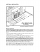
ELECTRICAL INSTALLATION Electrical procedures: The BUCKMATE is not pre-wired; an electrician must wire the 8UCKMATE into the home wiring system using No. 14 AWG (with ground wiring) as minimum in accordance with local wiring codes. (See Figure 4.) 1. Remove receptacle cover. 2. Remove receptacle from mounting box. 3. Run No. 14 AWG wire directly from house wiring in through the Field Connector in the lower right side of the BUCKMATE. Leave 4-6 inches of wire extending out of the box. 4.
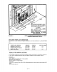
FINISHING Finishing can now be completed using the desired material In accordance with local building and fire codes. CAUTION: Do not cover any opening on the BUCKMATE; heat must be allowed to escape from the openings designed Into the unit. A grilled trim panel Is provided with the trim package to cover this area. Also, the grilled opening at the bottom front of the BUCKMATE cannot be blocked.
INSTALLING THE BUCK STOVE (See Page 48-49 for operation of the FP-201 Fireplace and for installation of gas logs) Install unit as follows: a. Carefully reinspect chimney connections, vent outputs and cabinet air intakes after finishing is completed. b. Thoroughly clean all masonry mud and debris from cabinet and surrounding environment. c. Ensure that BUCKMATE has not been damaged during masonry process. d. Remove protective plastic wrapping from fireplace. e.
i. Install the trim kit attaching it to the BUCKMATE or finished framing by using 1" screws to secure the trim panels in place. j. Remove cover plate from BUCK· MATE exposing receptacle. Roll up power cord so it will fit inside of cover box. Plug in power cord in receptacle. Replace cover plate. (See Figure 9). k. Stove Doors are made of high quality cast iron which resist warpage over conventional steel doors and should never require hinge adjustment.
FIRE CURTAINS Do not leave the fire unattended with the fire curtains open. Heat safely by burning with the curtains closed except for start-up of the fire and reloading of wood. PRECAUTIONS: Do not overfire. If unit or chimney connector glows, you are overfiring. Keep furnishings and other combustibles far away from the appliance.
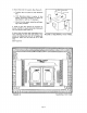
FP-201 REMOVAL/27000-B STOVE INSTALLATION The Fp·201 Fireplace may be removed and the Model 27000-B Stove may be installed into the ZC·3-01 BUCKMATE Cabinet in its place. Follow the procedures listed below to accomplish this change over: 1) Remove the front trim panel from the cabinet (3 vertical screws on each side and 2 screws on the power cord cover). 2) Spread the curtains to either side to give working room inside the firebox. Using a 9/16" socket and rachet.
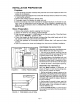
CHIMNEY MAINTENANCE Creosote and Soot - Formation and Need for Removal: When wood is burned slowly, it produces tar and other organic vapors, which combine with expelled moisture to form creosote. The creosote vapors condense in the relatively cool chimney flue of a slow-burning fire. As a result, creosote residue accumulates on the flue lining. When ignited, this creosote makes an extremely hot fire. Chimney Cleaning: 1.
A SECTION IV A SAFETY A Page 51
WOOD STOVE SAFETY Certain safety hazards are inherent in any wood stove installation. You should be aware of these so that a safe and proper installation can be made. 1. FAULTY CHIMNEY: An older masonry chimney should be thoroughly checked to be sure there are no holes or weak spots which could allow sparks or hot gasses to escape. HEAT CONDUCTION: Placing combustible materials too close to a stove or chimney can be a fire hazard.
SECTION V OPERATION Page 53
SECTION V · OPERATION This section of the manual is to help you get the maximum efficiency and utility from your BUCK STOVE. If you should experience any difficulty or have any questions concerning your BUCK STOVE. contact your BUCK STOVE dealer for assistance. BUILDING A FIRE FOR MAXIMUM EFFICIENCY: Because the BUCK STOVE burns wood and extracts heat so efficiently, a large fire is not necessary. A large fire not only wastes energy. it usually results in the home being too warm for comfort.
Guide To The Different Burning Qualities of Wood TYPE OF WOOD APPLE ASH BEECH BIRCH CHERRY CEDAR ELM HEMLOCK HICKORY LOCUST MAPLE OAK PINE EASE OF STARTING COALING QUALITIES 6.
Your BUCK STOVE can burn Bituminous soft type coal only (not Anthracite) with the optional BUCK STOVE'" COAL GRATE available at your Buck Stove dealer. Models available: CG·27000 for all Regular Buck Models: 27000·B and Big Buck Model: 28000. '------L\ COAL GRATE AND REFRACTORY SIDE LINING _Features include a separate stand for properly elevating grate for proper draft to fire coal. Can also be used for firedog (andirons). -Shaker for sifting ash. -Shaker arm with wood handle.
HELPFUL HINTS CURING THE PAINT ON YOUR STOVE: During the first several firings, burn small fires to cure the paint and to prevent damage to the finish. It is a good idea to flip the toggle. swi~ch to "MANUA~" position during these first firings so the blower will run continuously. This Will allow the pamt to cure at a slower rate and creates a better overall finish.
SECTION VI MANUFACTURER'S SUGGESTED PREVENTIVE MAINTENANCE Page 58
CHECK CHIMNEY A. The chimney should be cleaned as necessary to remove creosote, soot, leaves, birds' nests, etc. (Refer to Page 50, Creosote) B. A neglected chimney can eventually cause a draw restriction or can ignite and burn hot enough to cause damage to the chimney. C. For proper inspection the chimney should be cleaned. D.
CREOSOTE - Formation and Need for Removal When wood is burned slowly, it produces tar and other organic vapors, which combine with expelled moisture to form creosote. The creosote vapors condense In the relatively cool chimney flue of a slow·burnlng fire. As a result, creosote residue accumulates on the flue lining. When ignited this creosote makes an extremely hot fire. The chimney connector and chimney should be inspected at least once every two months.
, ) 8 .Your •.=It''U'Energy Answer ,. \. / (.- ~~ L_...J unmoto NEW BUCK CORPORATION P.O. Box 69 Spruce Pine, N.C.