
Technical data

Release 02/2008 Ver. 2.0 Installation Instructions: ZC-Series Controllers
TAPESWITCH CORPORATION Phone: 631-630-0442
100 Schmitt Boulevard 3 Fax: 631-630-0454
Farmingdale, New York 11735 www.tapeswitch.com
2. PRINCIPLES
The basic function of these controllers is to turn off or on a
single powerful machine in response to low power, low
voltage inputs. One load circuit is controlled, based on
sensing switches connected to the different zone inputs.
Depending on the model selected, there may be one, two,
three, or four independent input zones. A ‘RESET’ input
will re-energize the machine after a fault is removed.
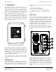
Two versions of each model are available, depending on the
application. In the Manual reset model, a specific reset
signal is needed to initiate output. In the AUTO reset
model, no signal is needed, and an output is initiated
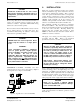
whenever all zones are fault-free. Figure 1 shows a four
zone, manual reset model.
Figure 1 – Front Panel of manual reset ZC-4
All models of the ZC Series controllers are packaged in a
NEMA 12 wall-mount enclosure. Mounted internally on the
enclosure door is an LED circuit board which holds the
indicating lamps. In the main part of the enclosure, a
subpanel holds the main or 'zone' printed circuit board,
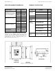
power transformer, and output contactor. Figure 2 shows
the internal arrangement of a ZC-4.
Zone controller operation is divided into three functions:
zone status monitoring, reset logic, and output contactor
operation.
ZONE SENSING
Zone sensing takes place continuously. Each zone is
independently monitored by a low-voltage DC current loop
circuit. When the zone is clear and fault-free, the zone
status light is green. However, a red status light will show
(and the controller will trip) upon any of the following
conditions:
- Loss of power to the controller
- Activation of the switch in that zone
- A short in the sensor or sensor wiring for that zone
- A break (open) of the sensor or sensor wiring for that
zone
RESET LOGIC
The reset logic acts to energize and de-energize the output
contactor. The reset logic continuously checks zone status,
and the reset command signal. When all zones are clear
and fault-free, and the reset signal is received, the contactor
is energized. In a manual system, there must be a separate
reset signal, usually from the front panel push button. An
AUTO Reset Model requires no separate signal, and resets
whenever the zones are clear and fault-free.
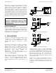
Both the reset logic, and zone monitoring logic components
are located on the 'Zone PCB' inside the cabinet. Figure 2
shows the typical layout of the inside of a four zone
controller.
Figure 2 - Internal Arrangement of a ZC-4
Because an AUTO Reset controller causes the output action
without further operator involvement, it is ideal for
machine automation. For example, a typical application
uses an industrial duty ControlMat to open a small door on
a reheating furnace. A worker carries a part to the furnace
using two handed tongs. The door opens automatically
when the worker steps on the mat. Operator safety is not
involved.