
Technical data

Release 02/2008 Ver. 2.0 Installation Instructions: ZC-Series Controllers
TAPESWITCH CORPORATION Phone: 631-630-0442
100 Schmitt Boulevard 4 Fax: 631-630-0454
Farmingdale, New York 11735 www.tapeswitch.com
When safety is involved, only the manual reset controller
should be used. Machine operation based on operator
presence-sensing is a dangerous application, forbidden by
OSHA in most instances. An example of a dangerous
AUTO Reset application would be a safety mat used in
front of an NC punch press. The mat only causes the press
to halt while the operator is on the mat. One worker was
injured when he stepped off a mat, onto the bed of a press
to clear a jam. When the jam cleared, the bed continued its
movement, pinning the worker. If the control had been
Manual Reset, the accident would not have occurred.
WARNING:
Do not use an AUTO Reset control in a safety
application. Serious death or injury may result,
particularly during unexpected operations or
during maintenance.
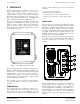
OUTPUT CONTACTOR
Each ZC Series controller houses a small, high-power
contactor, suitable for switching machine loads up to about
1.5 HP. The output contactor is designed to handle a single
machine load. It is located on the lower left of the main
internal panel, as shown in Figure 2.
3. APPLICATIONS
Section Two of this manual discusses the primary safety
considerations in selecting a Manual or Auto Reset
controller. Be sure you are familiar with the concepts
presented before applying a controller to a specific
machine.
The ZC Series controllers let you configure a sophisticated
array of sensors to control a single machine. When
multiple sensors are used, a frequent problem is the
difficulty in troubleshooting even a simple fault. Dividing
the sensors into zones and monitoring each zone
independently, greatly reduces downtime and
troubleshooting. The ZC Series provides 1 to 4
independent zones. For custom systems with even more
zones, contact TAPESWITCH.
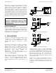
Each sensing zone may be connected in any of three
different wiring arrangements. A NO contact, a NC
contact, or a four wire FAIL-SAFE switch may be
connected to each zone. Figures 3, 4, and 5 show the
specific configuration to use when connecting each type of
sensor.
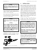
Figure 3- Connecting a Tapeswitch FAILSAFE sensor
Figure 4 - Connecting an NO switch
Figure 5 – Connecting an NC switch
Connecting multiple sensors on a single channel makes
troubleshooting more difficult and for that reason is NOT
recommended. TAPESWITCH recommends that no more
than two mat type sensors ever be used for a single zone.
Never bypass or disconnect a zone. Troubleshoot the
system by substituting components. If more, or fewer,
zones are needed, install a Tapeswitch controller with the
correct number of zones.
All channels are configured for FAIL-SAFE operation as
shipped. (User-supplied jumpers must be used to
reconfigure for other contact types). Note that the NO
connection is not supervised and should be avoided in some
applications.