
Technical data

Release 02/2008 Ver. 2.0 Installation Instructions: ZC-Series Controllers
TAPESWITCH CORPORATION Phone: 631-630-0442
100 Schmitt Boulevard 5 Fax: 631-630-0454
Farmingdale, New York 11735 www.tapeswitch.com
CAUTION
Consult the technical data for each sensor
being used to determine maximum units in a
configuration, operating limitations and other
requirements.
Observe the polarity shown. This means that terminals 1 &
4 and 2 & 3 respectively must be connected to the same
continuous conductor. Tapeswitch FAIL-SAFE sensing
switches are coded to indicate polarity.
The load contactor has both NO and NC contacts. It can be
used to switch both legs of a single phase load. It is
recommended that both legs be switched. A three phase
load contactor is optionally available.
WARNING:
NEVER switch the electrical ground. Never
switch only the neutral on a single phase
load.
WARNING:
Some particularly hazardous equipment,
such as power presses, require specific
levels of reliability, even when a fault occurs
to the controller. Be sure to check
applicable ANSI and OSHA documents for
specific requirements. Tapeswitch ZC and
ZCA controllers are not single-fault-tolerant.
Contact Tapeswitch for information on multi-
zone, multi-channel controllers.
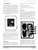
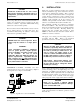
TAPESWITCH ControlMats, ArmorMats, and other
sensing devices are color-coded to show polarity. Figure 6
shows typical color coding for a Control Mat.
Figure 6 – Typical color code for ControlMats
4. INSTALLATION
When used to guard a hazardous location, the controller
must be a manual reset type, and be located in a safe area,
away from any hazards being guarded. This is common
sense. The operator should never be able to re-energize the
controls while in a hazard area. If the controller is best
located in a hazard area, then disconnect the front panel
“RESET” switch internally, cut off the connector, and
substitute a NO push button switch which is located in a
safe area. Use terminals 701 and 702 on the PC board.
These industrial controllers are designed for permanent
hard-wired installation. They must be securely mounted.
(There are predetermined locations for mounting hardware
on the rear of the controller). Mounting brackets are
standard with each controller. The enclosure is rated
NEMA 12, which means dust and water resistant. This is
suitable for most indoor locations.
All supply, zone sensing, and load wiring must be in
accordance with the NEC. Refer to the Technical
Specifications (Section 2) for data on permissible loads.
CAUTION:
Observe the NEC when wiring Tapeswitch
controllers, specifically Articles 300 and 310.
Be sure that all wiring is properly sized for
the load by referring to Table 310-17. Be
sure to connect the supply voltage to the
contactor common terminals and the load to
the NO or NC terminals. Failure to adhere to
the NEC may result in serious fire or injury.
High Voltage - Electrocution Hazard. Live
power may be present on the transformer.
Be sure that the unit is voltage-free before
installing or servicing.
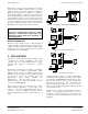
Power (120 or 240 Vac) must be supplied to the controller.
Connect incoming power to the high voltage side of the
transformer. See Figure 2, and the diagram on the side of
the transformer. Power requirements are low, usually much
less than the 20 VA specified. If a 120 Vac load is to be
connected directly to the controller, insure that supply
wiring is properly sized to supply both load and controller.
CAUTION
Never try to convert a Manual RESET
controller to AUTO Reset operation. Damage
to the controller will result.
For 120 Vac operation, connect H1 to H3, and connect H2
to H4 on the transformer. For 240 Vac operation, connect
H2 to H3 only.