
User's Manual
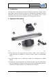
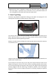

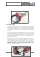
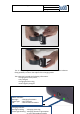
Table Of Contents

User Manual-Smart Tag Location
Version:
1.8
Date:
07-04-14
Page:
6 of 12
© buddi Ltd 2012
Talbot House, 17 Church Street, Rickmansworth, Hertfordshire WD3 1DE.
The fitting of the strap will create a closed optical circuit which is continuously
monitored by the Smart Tag.
4. Smart Tag Operation
The Smart Tag communicates via GSM to a server based monitoring platform, which
interprets the data provided to populate a web portal user interface. The data sets
include the following:
• Event Time.
• GPS Location (Intervals can be defined, or a real-time request made).
• Geofence Data (Virtual zones for inclusion or exclusion set by map data).
• Position Type (GPS, RF Beacon).
• Speed of Motion.
• Battery Level.
• Charger On / Off.
• Signal Strength.
• Strap On / Off (Off includes tampering or cutting).
• Alerts (Based upon one or more of the above).
Alerts can take the form of notifications within the web portal, by e-mail, SMS to
mobile phone notifications or vibration feedback within the Smart Tag on the
subject.
When in proximity to an RF Beacon, the Smart Tag will not attempt to achieve new
GPS fixes, resulting in significantly less demand on battery power.
5. Smart Tag Removal
Note any obvious sign of damage to the Smart Tag, or Strap in accordance with
local protocol.
When removing the Smart Tag from a subject protective gloves should be worn.
Check that the locking plates are complete, correctly located and undamaged. If
locking plates are damaged, follow local protocol which may include cutting the
strap and retaining evidence if necessary.
With no locking plate damage, use the removal tool to release the strap at one
end.
Using the release tool, engage the plastic jaws over the Smart Tag and begin to
squeeze the handles together. The jaws will self-locate to the correct position
and the release pins will puncture the Locking Plate, continue to squeeze until
the Strap is released. Only one end of the Strap will be released, this is indicated
by the red markers on the end of the release pins.