
Install Instructions


6
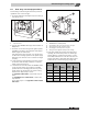
Commissioning the heating system
Logano G234X - Technical specifications are subject to change without prior notice.
32
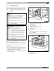
13. Check nozzle pressure. To set the nozzle pressure
according to Tab. 11 while the boiler is operating, the
safety screw for setting the nozzle pressure [3] on the
gas valve must be removed. Turn the adjustment screw
clockwise to increase the nozzle pressure. Turn the
adjustment screw counterclockwise to decrease the
pressure.
14. Record the value set in the commissioning log
(Æ page 35). To set the nozzle pressure, screw the
safety screw for setting the nozzle pressure [3] back
into the gas valve.
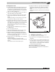
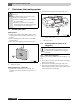
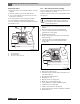
Fig. 34 Gas valve
1 ON/OFF button (at ON position)
2 Screw plug for gas connection pressure test port
3 Safety screw for nozzle pressure setting
4 Screw plug for nozzle pressure test port
5 Safety screw for ignition nozzle pressure setting
15. Observe pilot flame through the inspection hole in the
burner cover (Æ Fig. 32 page 31).
16. The flame must surround the flame rod by 1/2 to
1 1/2 inches (15 to 40 mm). If this is the case continue
with step 20.
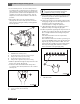
Fig. 35 Correct pilot flame setting
1 1/2 to 1 1/2 Inch (12.7 to 38.1 mm)
2 Pilot flame
17. If the ignition flame is too small or too large, the nozzle
pressure for pilot burner must be adjusted with the
corresponding adjustment screw.
18. Remove the safety screw for ignition nozzle pressure
setting (Fig. 34, [5]). Turn the inner adjustment screw
clockwise to reduce the pilot flame and
counterclockwise to enlarge the pilot flame.
19. After adjustment tighten the pilot burner pressure
adjustment safety screw (Fig. 34, [5]) again.
20. Observe pilot flame [1] through the inspection hole in
the burner cover (Æ Fig. 32, page 31). The flame must
have a steady and fixed contour and generally has a
bluish color.
If the main burner flame meets the requirements,
proceed with step 21.
If the main burner flame is too weak or is yellow or goes
out, turn the ON/OFF switch on the gas shut-off valve
(Fig. 34, [1], page 32) clockwise to OFF. Close the
gas shut-off valve and disconnect the heating system
from the power supply and contact the customer
service technician or the gas supply utility.
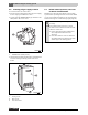
Fig. 36 Main burner
1 Main burner flame
The adjustment screw for the pilot ignition
pressure setting is behind the pilot burner
adjustment safety screw (Fig. 34, [5]).