6 720 804 44 0-00.2T Gas boiler WARNING! Installation, adjustment, modification, operation or maintenance of the heating system carried out by unqualified personnel may result in property damage, personal injury, and loss of life. The directions of this installation and maintenance manual must be followed precisely. Contact a qualified service company, service provider or the gas company if support or additional information is required.
Contents Contents 1 2 Safety considerations . . . . . . . . . . . . . . . . . . . . . . . . . . . . . . . . . 3 1.1 Key to symbols . . . . . . . . . . . . . . . . . . . . . . . . . . . . . . . . . 3 1.2 Safety instructions . . . . . . . . . . . . . . . . . . . . . . . . . . . . . . 3 Product Description . . . . . . . . . . . . . . . . . . . . . . . . . . . . . . . . . . . 2.1 Correct use . . . . . . . . . . . . . . . . . . . . . . . . . . . . . . . . . . . . 2.2 National regulations . . . . . . . . . .
Safety considerations 1 Safety considerations 1.1 Key to symbols Warnings Warnings in this document are identified by a warning triangle printed against a grey background. Keywords at the start of a warning indicate the type and seriousness of the ensuing risk if measures to prevent the risk are not taken. The following keywords are defined and can be used in this document: • NOTICE indicates a situation that could result in damage to property or equipment.
2 Product Description 2 2.3 Product Description The boiler is a low temperature gas boiler. The boiler consists of the following main components: • Ignition module and adjustable boiler temperature controller • Boiler jacket and front door • Boiler block with insulation • Burner The ignition module and adjustable boiler temperature controller monitor and control all electrical and operational components of the boiler.The boiler jacket prevents energy loss and acts as soundproofing.
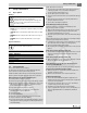
Dimensions and Connections 3 3 Dimensions and Connections 2 3/8 VK 1¼" GAS ½" EL ¾" (GAS ½")* RK 1¼" 6 720 804 440-02.1T Fig. 2 Back, side and front view, measurements in inches * optional connection VK Boiler supply RK Boiler return EL Boiler drain GAS Gas connection Dimensions Boiler size 18/3 25/4 32/5 Boilerinput Btu/hr 74000 103000 132500 A Inches 13 1/8" 16 3/4" 20 3/8" B Inches 8" 8 2/3" 9 1/2" Vent connection II Inches 5" 5" 6" Min.
4 4 Scope of delivery Scope of delivery ▶ Check packaging upon receipt of delivery for damage. ▶ Check delivery for completeness.
Placing the boiler 6 ▶ Place the boiler at its final postion. 5.2 Lifting and carrying the boiler The boiler can be picked up at the both long sides of the boiler as shown. 1 CAUTION: Risk of injury due to carrying heavy loads. ▶ Lift and carry the boiler with at least four people at the designated side panel locations. 2 3 6 720 804 440-07.1T Fig. 7 [1] [2] [3] 6.
7 7.2 Boiler installation Connecting the heating system 3 NOTICE: Boiler damage due to moisture. ▶ Protect the components of the gas ignition system from moisture (dripping, spray, rain) during installation of the boiler, during operation and during maintenance work (such as replacing the pump, replacing the control, etc.). NOTICE: System damage due to overheating as a result of a low water condition.
Boiler installation Installation of B-kit The relief valve and the pressure/temperature gauge are mounted on the boiler supply manifold which is attached to the VK (supply) connection of the boiler (included in B-kit). Installing boiler supply VK: ▶ Remove factory installed plastic inserts from boiler supply (VK), boiler return (RK) and boiler drain (EL) connections.
7 Boiler installation Description of field installed wiring connections using factory supplied junction box. ▶ Remove two knock-outs from the left side of boiler panel to route electrical feed and pump power into junction box. ▶ Route electrical power from the outside into junction box. ▶ Install a metal strain relief for the incoming power line on outside of left boiler jacket panel. ( figure 12). ▶ Just use supplied wiring nuts and double proper wiring before powering up the boiler.
Boiler installation Gas carrying capacity ( chapter 16, page 29) Nominal diameter of iron pipe (inches) 1/2 3/4 1 1 1/4 1 1/2 Equivalent lengths for pipe fittings in feet Pipe fitting type 90°Shut-off angle valve T-piece Gas shut-off Equivalent lengths in feet 1.4 2.7 0.3 0.80 2.1 4.1 0.5 1.25 2.6 5.2 0.6 1.6 3.5 6.9 0.8 2.15 4.0 8.0 0.9 2.50 7.4.2 Installation at high altitudes The boiler is designed for installation at altitudes below 8500 feet above sea level.
8 Check openings for combustion air supply and venting ▶ Open fill valve for additional filling. ▶ Set static system pressure to at least 15 psi at indicated on pressure relief valve ( figure 15). ▶ Close fill valve and remove fill hose for fill valve. Check openings for combustion air supply and venting NOTICE: Boiler damage and operating faults due to missing or inadequate openings for combustion air and venting of the boiler room.
Requirements for connection to chimneys or venting systems (crawl space or attic). The shortest dimension of all inlet and outlet openings must not be less than three inches. ▶ If there is a direct connection to the outside, each opening must have a minimum cross-section of one square inch per 4000 Btu/h of the total combustion output of all gas-fired appliances inside the closed room.
11 Placing the heating system in operation fastened to prevent it from hanging. A support must be installed at least every five feet. Fasten every connection with at least three (3) corrosionresistance sheet metal screws.The end section of the flue pipe must connect to the inside of the chimney smoke duct. ▶ Connect vent damper plug into the terminal bar as shown in the circuit diagram.
Placing the heating system in operation ▶ Check all combustion air and all flue gas ducts and openings. ( chapter 8, page 12 and chapter 9, page 13). WARNING: Danger of explosion if you smell gas there is danger of explosion! ▶ No open flame! No smoking! ▶ Prevent spark generation.
12 Final start-up procedures 11.1.2 Turning on heating system The boiler is fully functional with the factory-installed boiler temperature controller and field installed and connected vent damper. WARNING: Risk to life from fire or explosion. ▶ Never use excessive force on the ON/OFF knob ( figure 23). ▶ Turn ON/OFF knob only by hand. ▶ Never use tools to turn knob. ▶ If you are unable to turn the knob by hand, do not try to repair it. ▶ Call Buderus technical service for assistance.
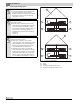
Final start-up procedures Natural Gas [inch W.C.] 3.5 3.5 3.5 GC 144 II 18 25 32 12 LP [inch W.C.] 8.8 8.6 8.7 Table 10 Orifice pressure at 60°F / 30" Hg. These values are only valid in the U.S.A. and only for elevations from 0-8500ft. 1 2 3 6 720 804 440-25.1T Fig. 25 Main burner [1] Checking flame rod ▶ Test the flame rod by closing the gas shut-off. The main burner flame ( figure 25) and the ignition flame are extinguished.
12 Final start-up procedures ▶ Turn gas valve ON/OFF knob clockwise to OFF position. ▶ Close main gas shut-off. ▶ Disconnect heating system from the power source and set the thermostat to the lowest setting. ▶ Remove pressure measuring nipple and pressure gauge for measuring gas pressure and orifice pressure from the gas valve, and close the openings with the screw plugs.
Start-up protocol 13 13 Start-up protocol Please check off all startup steps and record measurements in the appropriate tables. Start-up procedure 1. Type of gas 2. Has the leak test been completed? 3. 5. Check combustion air, inlet and outlet openings and flue gas connection Check the equipment (correct orifices? See below) and convert gas type if necessary Fill boiler with water and bleed complete heating system 6. 7. 8.
14 Taking the heating system out of operation 14 Taking the heating system out of operation 15 Boiler inspection and maintenance 14.1 Normal system shut-down 15.1 Why is regular maintenance important? ▶ Turn ON/OFF switch (emergency shutoff switch) to OFF position. This shuts off power to the boiler and all of its components (e.g. burner, temperature controller). ▶ Turn ON/OFF knob on gas valve clockwise to OFF position. NOTICE: System damage due to freezing.
Boiler inspection and maintenance 15 1 2 1 6 720 804 440-40.1T Fig. 32 Correct ignition flame setting 6 720 804 440-38.1T [1] [2] Fig. 30 Gas valve [1] 15.5 ON/OFF knob (shown in ON position) Cleaning the boiler The boiler can be cleaned with brushes and/or by wet cleaning. Cleaning tools are available as accessories. Inspecting the ignition burner ▶ Observe the ignition burner through the sight glas window ( figure 31).
15 Boiler inspection and maintenance 15.5.1 Cleaning the boiler with brushes Burner removal 2 WARNING: Risk to life from electric shock. ▶ Before opening a unit: disconnect electrical power and lock to prevent accidental reactivation. ▶ If cables are connected incorrectly the system may not operate correctly with possibly dangerous consequences. ▶ After maintenance test the heating system for proper function.
Boiler inspection and maintenance 15 15.5.2 Wet cleaning (chemical cleaning) For wet cleaning use a suitable cleaning agent depending on the degree of build-up of dirt (soot or scale). Use the same procedure as described for cleaning with brushes ( chapter 15.5.1, page 22). Observe the directions for use of the cleaning agent. In some case you may need use a different procedure from that described here. ▶ ▶ ▶ ▶ ▶ ▶ ▶ ▶ ▶ ▶ ▶ ▶ ▶ ▶ Cover control with foil to prevent entry of spray into the control.
15 Boiler inspection and maintenance ▶ Rinse out burner rods with a water jet; hold burner so water enters all slots of the burner rods and drains back out. ▶ Follow instructions in „Final start-up procedures“. ▶ Test low water alarm. ▶ Check area around boiler for hazards. Complete the maintenance protocol to confirm that all maintenace work has been conducted. Sign the maintenance protocol and discuss it with the owner of the heating system. 6 720 804 440-51.1T Fig.
Boiler inspection and maintenance 15.7 15 Maintenance protocol Please check off the maintenance work as it is completed and record the measured values. Follow the instructions on the following pages. Maintenance work 1. Inspection of the flue system including combustion air, inlet and outlet openings 2. Gas manifold pressure Page page 20 Date: page 20 3. Inspection of burner page 11 page 20 4. Cleaning of boiler page 21 5. Cleaning of burner page 23 6. 7. 8.
15 Boiler inspection and maintenance # Date: Date: Date: Date: Date: –––––––inches W. C. –––––––inches W. C. –––––––inches W. C. –––––––inches W. C. –––––––inches W. C. –––––––inches W. C. –––––––inches W. C. –––––––inches W. C. –––––––inches W. C. –––––––inches W. C.
Boiler inspection and maintenance 15.8 15 Troubleshooting the GC 144 II Equipment required: Wiring diagrams ( chapter 17, page 30) and voltage detectors for 120 VAC and 24 VAC. Start Close gas valve. Set thermostat (control) to require heat (vent damper open). Switch on power. No Observe ignition sparks in gap between electrode and sensor through sight glass. No Open main gas valve. Ignition flame is burning.
15 Boiler inspection and maintenance START PHASE 1 Ignition attempt Room thermostat (control) signals heat requirement Vent damper (if installed) opens. Ignition spark generator operates • ignition gas valve opens. Ignition burner operation Ignition flame burns, automatic or ignition flame does not burn, ignition signals steady ignition pilot assembly starts ignition atflame. tempt, switches off after 90 seconds. Pilot flame stand by • ignition spark generator stops. • main gas solenoid valve opens.
Technical specifications 16 16 Technical specifications Main gas orifice identification and manifold pressure for Natural gas Boiler size Number of orifices 18/3 25/4 32/5 2 3 4 Main gas orifice identification for elevations from [feet] 0–8500 ft 1) 285 275 270 [in ft3/h] [inch W.C.] 68.8 95.8 123.3 3.5 3.5 3.5 Table 14 Main gas orifice identification and manifold pressure for Natural gas at 60° F / 30 inch HG. These values are only valid in the U.S.A. and only for elevations from 0 – 8500 ft.
1 Circulator N L Emergency Shut-off Switch (by others) Junction Box yellow white Boiler Sensor black R 2 3 Fuse 1,25AT Optional Vent Damper Plug Wiring diagram gas-boiler GC 124 USA / GC 144 USA Intermittent ignition green yellow white L2 L1 C1 C2 ZC ZR B1 B2 Plug W orange black MV GND Plug PV MV/PV Wiring diagram : Edition : 8718588198 Drwg. no.
US N M Wire nut Wire nut Circulator Wire nut C1 K2 L1 K2 TR High Limit W T-Stat R K1 B2 4 24VGND Spark To Pilot Burner Flame roll out safety shutoff switch Blocked vent switch 24V 3 2 1 Fuse 1,25AT B1 K1 Wiring diagram gas-boiler GC124 USA / GC 144 USA Intermittent ignition L2 Transformer S8600H GND GND green Emergency shut-off switch PV Main PV PV/MV PV MV Gas valve Pilot blue Wiring Schematic GC 124 / GC 144 white Logano GC 144 II – 6 720 808 893 (2014/04) MV