
77501 Applications Manual


Applications manual
| 19
Panel Radiator
Applications Manual
Panel Radiator Applications Manual | 11.2019 Technical specifi cations are subject to change without prior notice
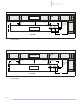
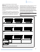
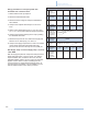
Option 3: Individual Supply and Return System
(home run).
Options 2 and 3 above can be installed in a multiple loop
fashion where several one-pipe systems are connected
between a common supply and return manifold. Assure
adequate fl ow in all piping systems when using monofl ow
loops and/or diverter valve loops. Isolation and balancing
valves are recommended on each loop for service and
fl ow control.
A properly sized pump operating on constant circulation
can supply water to all loops. A single Grundfos UP15-42
or equivalent can handle up to 3 diverter valve loops; use
a Grundfos UP26-64 or equivalent for 4 to 6 loops. Size
the main piping for the combined fl ow in all branches,
DISCLAIMER: Application drawings in this manual are conceptual only and do not purport to address all design, installation, code, or safety considerations. The diagrams in this manual are for
reference use by code officials, designers and licensed installers. It is expected that installers have adequate knowledge of national and local codes, as well as accepted industry practices, and
are trained on equipment, procedures, and applications involved. Drawings are not to scale.
Refer to the boiler, control and module installer manuals for additional detailed information!
1 2
1 2
1 2
1 2
1 2
1 2
1 2
1 2
1 2
Option 1: One-Pipe System with Venturi Tees or Monoflow Tees.
Option 2: One-Pipe System with Diverter Valves.
Option 3: Individual Supply and Return System (Home Run).
System Supply System Return
System Supply
System Return
System Supply
System Return
Fig. 11 One-Pipe System Options
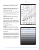
following the guidelines in Table 10. Refer to the Pressure
Drop Curves (Fig. 14 & 15) on pages 30 & 31 for
estimating the pressure drop through each radiator when
using monofl ow tees. Use the Pressure Drop Diagram on
page 30 for a one-pipe system with diverter valves. Use
the approximate fl ow rate through the radiator and fl ow
setter valve setting to read off the pressure drop. Size the
circulator based on total fl ow and overall system pressure
drop. Thermostatic heads are required in this
arrangement for individual temperature control.
Ensure all supply and return piping is sized properly
to avoid restriction and noise.