Installation and maintenance instructions Solid fuel boiler CAUTION! Observe the safety instructions of this installation and maintenance manual before placing the boiler in operation. DANGER! If installation, adjustment, modification, operation or maintenance of the heating system is carried out by an unqualified person, this may result in danger to life and limb or property damage. The directions of this installation and maintenance manual must be followed precisely.
Contents Contents 1 Safety instructions and symbol key . . . . . . . . . . 3 1.1 Explanation of symbols . . . . . . . . . . . . . . . 3 1.2 General safety instructions . . . . . . . . . . . . 3 2 Information about the appliance . . . . . . . . . . . . 4 2.1 Designated use . . . . . . . . . . . . . . . . . . . . . 4 2.2 Standards, regulations and directives . . . . 4 2.3 Installation tips . . . . . . . . . . . . . . . . . . . . . 4 2.4 Operating tips . . . . . . . . . . . . . . . . . . . . . . 4 2.
Safety instructions and symbol key 1 Safety instructions and symbol key 1.1 Explanation of symbols Safety instructions in the text are marked with a warning triangle and printed on a gray background. Signal words are used to indicate the level of risk if countermeasures are not taken. – Caution indicates that minor damage to property may occur. – Warning indicates that minor personal injury or severe damage to property may occur. – Danger means that severe personal injury may occur.
2 2 Information about the appliance Information about the appliance This installation and maintenance manual contains important information for the safe and correct installation, initial commissioning, and maintenance of this boiler. 2.4 This manual is intended for qualified technicians with experience and training in heating systems. V The boiler may only be operated by adults who are familiar with the instructions and boiler operation.
Information about the appliance 2.5 Air supply Danger: Risk of fatal injury from lack of oxygen in the boiler room! V Make sure there is adequate fresh-air ventilation by providing air vents to the outside. V Point out to the system operator that those air vents must remain open. Warning: System damage and risk of injury in case of incorrect commissioning! Lack of adequate air for combustion can lead to creosote formation.
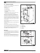
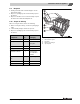
2 2.8 Information about the appliance Product description The Logano G201 is a solid fuel boiler and approved for fueling with coal and wood blocks. The boiler consists of: – Air vent [1] – Ash pan door [2] – Fuel filler door [3] – Firing controller [4] with rod and chain – Aquastat [5] – Manifold [6] with pressure relief valve and pressure/ temperature gauge and supply manifold. Using the firing controller [4], the desired boiler water temperature is set and limited to this maximum value.
Information about the appliance 2.9 2 Disposal V Packing materials made of wood and paper can be burned in the boiler. V Dispose of packaging in an environmentally responsible manner. V Dispose of old devices in an environmentally responsible manner at an authorized disposal site. 2.10 Scope of delivery When receiving the boiler, observe the following: V When receiving the delivery, check if the packaging is intact. V Check that all package contents are present.
2 Information about the appliance 2.11 Dimensions and specifications C S Fig.
Information about the appliance 2 2.11.1 Technical specifications Unit Boiler sizes 27 35 40 Rated output wood1) BTU/HR 96000 125000 145000 Rated heat output coal BTU/HR 108000 140000 160000 Efficiency % 78 – 85 Flue gas temperature °F 212/392 Burning time (rated output) h 2 –4 Content of the fuel filler space Cu.Ft / Lbs 2 3/8 / 153 3 3/8 / 196 4 3/8 / 254 inches 15 ¼ 19 ¼ 27 ¼ Water capacity gal 9 10 12 CO2 content (max) % 20.6 20.7 20.
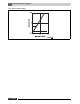
2 Information about the appliance 2.11.2 Flow resistance graph Fig. 5 10 Flow resistance depending on the volumetric flow rate Logano G201 - Subject to technical modifications.
General instructions about the fuels wood and coal 3 General instructions about the fuels wood and coal Wood and coal can be used as fuels. Heating value (with wood humidity of 20 %) Danger: Danger of fatal accident due to escaping carbon monoxide (CO)! In case of firing with brown coal, the boiler can silt up and CO can escape. V Do not use brown coal for firing.
4 4 Transport and set-up Transport and set-up This chapter describes how to transport the boiler block safely and how to set it up in the boiler room. Bring the boiler block into the boiler room with a dolly and transport belts. Danger: Risk of fatal injury! Falling loads can cause fatal injuries. V Please observe the safety instructions for transporting heavy loads with a dolly. V Use personal protective equipment (e.g. helmet, safety shoes, protective gloves).
Transport and set-up 4.1 4 Transporting the boiler block with transport aids Warning: Danger of injury during transport! Improperly-secured transport goods can cause injuries. V Use only suitable transport aids, e.g. a trolley with strap, a stair or step trolley. V Secure the load against falling. The boiler block is on a special pallet and is secured with transport bands. V Loosen and remove the transport bands on the Europallet.
4 Transport and set-up 4.2 Installing the boiler block 4.2.1 Installation requirements for the set-up room Caution: Risk of system damage due to frost! If the heating system has been switched off, it may freeze up in cold weather conditions. V Install the heating system in a frost-free room. Danger: Risk of death from explosion and fire! The storage of explosive or easily-flammable materials near the boiler can create lifethreatening situations.
Transport and set-up 4 Installing and aligning the boiler block V Loosen and remove the transport bands on the special pallet. Warning: Risk of injury from carrying heavy loads! Lifting heavy loads can cause injuries. V Always lift the boiler block with at least two people. V Lift the boiler block from the special pallet. V Set the boiler block on the prepared base.
5 Installation 5 Installation 5.1 Fitting the flange of the supply and return connections The flange for the supply connection [1] is in the combustion chamber. The flange for the return connection [2] is fastened to the rear wall with two nuts at the factory. V Remove the flange for the supply connection [1] from the combustion chamber. V Loosen the nuts on the flange for the return connection [2] and remove the flange. V Place the gaskets [3] on the flange.
Installation 5.2 5 Fitting the side panels and rear wall The boiler jacket and the installation material are packaged in a carton and are on a separate pallet. 5.2.1 Fitting the front tie-bar V Remove the counternut [4] and washer [3] from the anchor rod [2]. V Fit the front tie-rod [1] on the anchor rod [2]. V Fit the washer [3]. V Tighten the front tie-bar [1] with counternut [4]. Fig. 10 Fitting the front tie-bar 1 2 3 4 5.2.
5 Installation 5.2.3 Fitting the side panels The fitting sequence is the same for the right and left side panels; proceed as follows: V Loosen the counternut [2] of the lower anchor rod [4] (front) until there is a small gap between the counternut and the nut. V Hook the front connecting bracket [1] of the side panel into the resulting gap. The front connecting bracket of the side panel sits on the anchor rod [4]. V Hook the rear part of the side panel into the anchor rod. Fig.
Installation 5 5.2.4 Fitting the rear panel V Hook the rear panel [1] below into the tabs [2] of the side panels. V Fasten the rear panel [1] above with two bolts to the side panels. Fig. 14 Fitting the rear panel 1 2 5.3 Rear panel Tabs Sealing the firing controller V Remove the plugs [1] for the connection of the firing controller. The connection is in the front part in the upper right. V Seal the firing controller [3].
5 5.4 Installation Sealing the immersion sleeve (Aquastat scope of delivery) V Remove the plugs [2] for the connection of the Aquastat. The connection is on the top in the middle of the rear section [3]. V Seal the immersion sleeve [1] (Aquastat scope of delivery) in the rear section [3]. Fig. 16 Sealing the immersion sleeve 1 2 3 5.
Installation 5 V Insert the front boiler cover [3] so that the firing controller [4] goes through the opening. V Tighten the front boiler cover [3] with two bolts on the tie-rod. V Insert the rear boiler cover [1] so that the two edges [2] of the rear boiler cover [1] are inserted into the front boiler cover [3]. V Insert the side hooks of the rear boiler cover [1] into the side panels. V Tighten the rear boiler cover [1] with two bolts on the tie-rod. Fig.
5 Installation V Fasten the controller chain rod [1] to the air vent of the ash pan door. V Connect the controller chain rod [1] and hexagon bolt via a chain (included). Fig. 20 Installing the controller chain rod 1 Controller chain rod Installing the regulator screw V Screw the regulator screw [1] into the air vent of the ash pan door until this is a slight crack open (0.2 inches). Fig. 21 Installing the regulator screw 1 22 Regulator screw Logano G201 - Subject to technical modifications.
Installation 5.7 5 Installing the front faceplate V Install the protective bar [3] in the front faceplate [1]. V Insert the faceplate [1] with protective bar [3] and fasten with two bolts to the side panels. V Affix the appliance insignia plate [2] to the faceplate [1]. Fig. 22 Installing the front faceplate 1 2 3 5.8 Front faceplate Appliance insignia plate Protective bar Installing the Aquastat V Drill four holes in the rear boiler cover [4] for fastening the Aquastat [1] (Æ Fig. 23).
6 6 Openings for combustion air supply and venting Openings for combustion air supply and venting To ensure an adequate combustion air supply and venting of the heating system suitable measures must be taken in accordance with the NFPA 31 Air for Combustion and Ventilation, or the local codes. In Canada, the regulations in accordance with CSA/CGA–B 149.1 and 2 Installation Codes apply.
Openings for combustion air supply and venting 6 – If there is a direct connection to the outside, each opening must have a minimum cross-section of one square inch per 4000 Btu/h of the total combustion output of all combustion-fired appliances inside the closed room.
7 Installation 7 Installation 7.1 Air intake and flue gas connection 7.1.1 Notes about air intake connection Danger: Risk of fatal injury from lack of oxygen in the boiler room! V Make sure there is adequate fresh-air ventilation by providing air vents to the outside. V Point out to the system operator that those air vents must remain open.
Installation 7 7.1.3 Flue pipe installation Fig. 24 shows the proper flue gas connection with additional air equipment. Observe the following during the installation of the flue gas connection: V Install a flue pipe connection with an inspection aperture for cleaning. V Fasten the flue gas connector piece to the boiler. V Feed the connector into the flue gas system on a short, ascending path. Avoid deflections, especially those with an angle of 90°. V Fasten and support connectors sufficiently.
7 7.2 Installation Making the water connections Caution: Risk of system damage due to leaking connections! V Support the pipes to the boiler to prevent them from being under stress. 7.2.1 Installing B-Kit The pressure relief valve [6] and the pressure/temperature gauge [1] are mounted on the boiler supply VK using the return manifold [5] (included in B-Kit). V Seal the double nipple [2] with R 1¼ " threads NPT. V Seal 90° 1¼ " NPT street elbow [3] on double nipple.
Installation 7.3 7 Filling the heating system and checking connections for leaks Before commissioning the heating system, check it for soundness to avoid leaks occurring during operation. Warning: Risk to health due to pollution of drinking water! V Always observe the regulations and standards applicable in your jurisdiction for the prevention of contamination of drinking water (e.g. by water from heating systems).
7 Installation V Seal pressure relief valve connection (Æ Fig. 25, page 28) and all other open connection with blind plugs. V Isolate the expansion tank from the system by closing the valve. V Open the mixing and shut-off valves on the heating water side. V Connect the hose to the water tap. Push hose onto the hose connection of the boiler fill & drain valve, fasten with a hose clip, and fill with water. V Open the fill & drain valve. Slowly fill the heating system.
Commissioning 8 8 Commissioning This chapter explains how to commission the heating system for the first time. V Complete the commissioning report during this process (Æ Chapter 8.6, page 36). Danger: Risk of fatal accident due to chimney fire! V Before initial commissioning, have the chimney checked by the local chimney installer. V If soot ignites, close all ventilation ducts to the boiler and the fuel space door. V Check flue pipe for leaks. V Do not make any constructional changes to the boiler.
8 8.1 Commissioning Bring the system up to operating pressure Bring the system up to the normal operating pressure before commissioning. Caution: Risk of damage to system due to temperature stresses. If you fill the heating system when it is hot, the resulting temperature stresses can cause stress cracks. The boiler will then leak. Fig. 28 Pressure/temperature gauge V Only fill the heating system when cold (the flow temperature should be no more than 100 °F).
Commissioning 8.3 8 Heating up the boiler Warning: Risk of system damage due to incorrect operation! Overfilling the ignition chamber with fuel can cause overheating and damage to the boiler. V Adjust fuel quantity to the energy absorption of the heating system (Æ Chapter 8.4, page 35). Decisive for clean burning in the boiler are the correct operation of the boiler and a sufficient flue draft for the flue gas system. V Open the ash pan door.
8 Commissioning V Insert a layer of paper [2]. V Insert a 3 to 4 inch layer of fuel (thin kindling, coal or coke) on the paper layer [2]. Do not use any thick logs. V Light the fuel inside the boiler. V If you are using solid accelerant (coal igniter), light the accelerant outside of the boiler and then place it on the ignition material. V Fold the front grate upwards and insert the segment plate. V Leave the ash pan door slightly open. V Let the fuel burn for 15 – 20 minutes until there are embers.
Commissioning 8.4 8 Energy absorption The energy absorption of the heating system (consisting essentially of boiler and buffer storage) depends on the actual value of the water temperature of the buffer storage. For economical operation of the heating system, the fuel quantity used must be adjusted to the respective energy absorption. This way, overheating of the boiler is avoided and pollutant emission is reduced. 8.
8 8.6 1. Commissioning Commissioning log Commissioning work Page Fill heating system and check for leaks 29 – Heating system filling pressure 2. Readings taken Comments ____________ psi Bring the system up to operating pressure _________ psi – Bleed heating system – Test pressure relief valve – Adjust the expansion vessel pressure (Æ expansion vessel documentation) 3. Check combustion air supply and flue system 4. Inform operator, hand over technical documentation 5.
Shutting down the boiler 9 9 Shutting down the boiler Warning: Risk of system damage due to frost! If the heating system has been shut down, it may freeze up in cold weather conditions. V When there is a risk of frost, protect your heating system against freezing up. V If there is risk of frost and you are not operating the boiler, empty the system. To shut the boiler down, let it burn off everything without artificially accelerating the combustion process.
10 10 Cleaning and maintenance Cleaning and maintenance Warning: Damage to system due to improper maintenance! Insufficient or improper maintenance of the boiler can cause damage and void warranty claims. Warning: Risk of system damage due to insufficient maintenance and cleaning! Larger quantities of ashes in the fuel space can cause overheating of and damage to the boiler. V Carry out regular, extensive, and professional maintenance of the heating system.
Cleaning and maintenance 10 10.1.1 Frequent cleaning The ashes must be removed from the combustion chamber/ash pan every 1 – 3 days. V Open the ash pan door [2]. V Fold the front grate downwards and remove the segment plate (Æ Fig. 30, page 33, and Fig. 31, page 33). V Tip the combustion residues into the ash pan. V Insert the segment plate and fold the front grate upwards. V Remove the combustion residues from the ash pan with the ash shovel [1]. Do not place hot ashes in plastic and waste containers.
10 Cleaning and maintenance Cleaning the flue gas header The flue gas collector [2] is cleaned via the inspection aperture. The inspection aperture is on the bottom of the flue gas collector and is sealed with the cleaning cover [1]. V Unscrew the two wing nuts on the cleaning cover. V Carefully remove the cleaning cover [1]. V Remove the combustion residues via the inspection aperture. V Close the inspection aperture with the cleaning cover [1]. Check that the gasket is seated correctly.
Cleaning and maintenance 10 10.3 Checking the flue gas temperature If the flue gas temperature is higher than stated in the specifications, the system must be cleaned again. It is also possible that the flue draft of the flue gas system is too high (Æ Chapter 2.11.1, page 9). Logano G201 - Subject to technical modifications.
10 Cleaning and maintenance 10.4 Inspections and maintenance log Carry out maintenance when the inspection of a system state indicates that this is necessary. The inspection and maintenance log also serves as a copying template. V Initial and date the servicing operations completed. Inspection and condition-based maintenance 1. Check general condition of heating system 2. Visual inspection and function check of the heating system 3.
Cleaning and maintenance 10 Date:_____ Date:_____ Date:_____ Date:_____ Date:_____ Date:_____ Date:_____ Company stamp/signature Company stamp/signature Company stamp/signature Company stamp/signature Company stamp/signature Company stamp/signature Company stamp/signature 1. 2. 3. 4. 5. 6. 7. 8. Tab. 10 Inspection and maintenance log (continued) Logano G201 - Subject to technical modifications.
11 11 Troubleshooting Troubleshooting Only use original Buderus components for repairs. Fault Cause Remedy Boiler output too low Calorific value of the fuel used is too low, humidity of the fuel is higher than 20 % Use prescribed fuel with prescribed humidity Operating conditions not adhered to Check flue draft, return temperature.
Parts lists 12 12 Parts lists Boiler block G201W US (Æ Fig. 42) Item Description Ordering no.
12 Item Parts lists Description Ordering no.
12 Parts lists 13 19 25 24 21 20 23 18 3 4 1 20 21 33 32 32 32 30 32 22 31 33 3 32 22 32 45 30 32 32 33 33 32 4 44 35 42 41 46 41 26 22 32 22 29 32 40 32 36 37 38 46 40 58 32 36 57 56 50 60 52 54 53 55 51 6720905317.aa.RS Fig. 42 Boiler block G201W US Logano G201 - Subject to technical modifications.
12 Parts lists Fittings rear (Æ Fig. 43) Item Description Ordering no.
Parts lists 12 10 13 15 14 2 1 4 4 10 20 25 21 10 3 10 9 9 16 17 9 18 8 5 26 10 27 7 13 6 15 14 20 21 29 6720905318.aa.RS Fig. 43 Fittings rear Logano G201 - Subject to technical modifications.
12 Parts lists Tank jacket (Fig. 44) Item Description Ordering no. G201W US 27/5 G201W US 35/6 G201W US 40/8 Remarks 1 Side panel L.h. 615 long 63021709 X 1 Side panel L.h. 715 long 63021710 1 Side panel L.h. 915 long 63021711 2 Side panel R.h. 615 long 63021704 2 Side panel R.h. 715 long 63021705 2 Side panel R.h.
Parts lists 12 8 7 5 2 6 13 13 13 13 13 4 3 13 Bu Lo ga no G2 de r u s 01 10 9 13 11 13 13 1 6720905319.aa.RS Fig. 44 Tank jacket Logano G201 - Subject to technical modifications.
13 13 Installation examples and electrical connection schemes Installation examples and electrical connection schemes Fig. 45 Wood coal boiler with optional dump zone (installation example) 6 Fig. 46 Wood coal boiler with optional dump zone (example, connection schemes) 52 Logano G201 - Subject to technical modifications.
Installation examples and electrical connection schemes 13 Fig. 47 Wood coal boiler with gas/oil boiler (installation example) Fig. 48 Wood coal boiler with gas/oil boiler (example, connection schemes) Logano G201 - Subject to technical modifications.
13 Installation examples and electrical connection schemes Fig. 49 Wood coal boiler with shunt pump (installation example) Fig. 50 Wood coal boiler with shunt pump (example, connection schemes) 54 Logano G201 - Subject to technical modifications.
13 Notes Logano G201 - Subject to technical modifications.