
Install Instructions
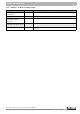
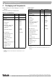
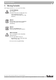
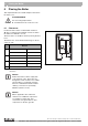

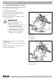
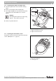
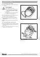
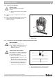
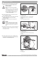
Table Of Contents
- 1 Safety Considerations
- 2 Product Description
- 3 Technical information
- 4 Packaging and Components
- 5 Moving the boiler
- 6 Placing the Boiler
- 7 Boiler block assembly
- 7.1 Assembly when delivered in sections
- 7.2 Check for leaks
- 8.2 Installation of water connections
- 8.2.1 Installing B-Kit:
- 8.2.2 Installation of boiler drain (included in B-Kit)
- 8.2.3 Installation of system components
- 8.3 Filling heating system and checking for water leaks
- 8.4 Burner installation
- 8.5 Providing a fuel supply
- 8.6 Aquastat installation
- 8.7 Electrical connections
- 8.7.3 Electrical connections and connection of additional components
- WARNING!
- 8.7.4 Strain relief installation
- 8.8 Jacket panel installation
- 9 Placing the boiler in operation
- 9.9 Start-up protocol
- 11.3 Boiler cleaning
- 11.6 Inspection and maintenance protocols
- 16 Table of Key Words

Packaging and Components4
12
Installation and maintenance instructions Logano G215 US oil/gas-fired boilers • Issue 11/2004
We reserve the right to make any changes due to technical modifications.
4 Packaging and Components
z After delivery, check all packaging for concealed
damage.
z Check the delivery for completeness.
Boiler as assembled block
Boiler in parts
Component Qty Packaging
Boiler block 1 1 pallet
1
Control panel,
or aquastat
1 1 box
Jacket Package:
– Boiler jacket
– Insulation
– Burner door, burner door
cover and assembly
equipment
2
– Technical documents
B-Kit components:
– Supply manifold (11/4")
– 30 psi relief valve
– Boiler drain (¾")
– Pressure/temperature
gauge
– 90°-elbow (¾")
– Burner mounting studs and
washers
– Aquastat well (¾")
– Bushing 1" x ¾"
– Plug 1"
1
1
1
1
1
1 box on a
pallet
1 box
1
1 box
1
1 box
1
1 plastic
package
1 package
Tab. 9 Packaging
1
1 pallet
2
The screw-in feet are in the burner door and burner door cover
package.
Component Qty Packaging
Front, center and back sections 1 1 pallet
Control panel,
or aquastat
1 1 box
Jacket Package:
– Fittings
– Boiler jacket
– Insulation
– Burner door, burner door
cover and assembly
equipment
2
– Technical documents
B-Kit components:
– Supply manifold (11/4")
– 30 psi relief valve
– Boiler drain (¾")
– Pressure/temperature
gauge
– 90°-elbow (¾")
– Burner mounting studs and
washers
– Aquastat well (¾")
– Bushing 1" x ¾"
– Plug 1"
1
1
1
1
1
1
1 box on a
pallet
1 box
1
1 box
1
1 plastic
package
1
1 box
1
1 plastic
package
1 package
Tab. 10 Packaging
1
1 pallet
2
The screw-in feet are in the burner door and burner door cover
package.