Condensing gas boiler CAUTION! Before putting the boiler into operation read this manual carefully. DANGER! Improper installation, adjustment, alteration, service or maintenance can cause injury, loss of life or property damage. Refer to this manual. For assistance or additional information consult a qualified installer, service agency or the gas supplier. CAUTION! The operating manual is part of the documentation that is delivered to the installation's operator.
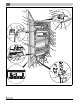
15 20 19 18 14 17 13 12 10 11 15 16 21 22 23 24 25 26 27 28 29 30 31 9 8 7 32 34 35 33 5 6 38 37 39 36 1 40 44 41 42 43 4 3 2 6720645916-01.TD Fig.
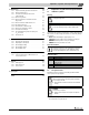
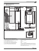
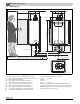
[1] [2] [3] [4] [5] [6] [7] [8] [9] [10] [11] [12] [13] [14] [15] [16] [17] [18] [19] [20] [21] [22] [23] [24] [25] [26] [27] [28] [29] [30] [31] [32] [33] [34] [35] [36] BC10 basic controller receptacle Installation option for room controller, e.g. RC35 Cover with user manual compartment BC10 basic controller, can be expanded e.g.
Contents 7.2.1 Installing function modules in the boiler . . . . . . . . . . . . 26 7.2.2 Installing function modules outside the boiler . . . . . . . 28 7.3 Electrical wiring diagram . . . . . . . . . . . . . . . . . . . . . . . . 29 Contents 1 2 Explanation of symbols and safety information . . . . . . . . . . . 5 1.1 Guideline to symbols . . . . . . . . . . . . . . . . . . . . . . . . . . . . 5 1.2 Safety instructions . . . . . . . . . . . . . . . . . . . . . . . . . . . . . .
Explanation of symbols and safety information 12 Maintenance . . . . . . . . . . . . . . . . . . . . . . . . . . . . . . . . . . . . . . . . 12.1 Prepare the heating system for maintenance . . . . . . . . 12.2 Remove the boiler door . . . . . . . . . . . . . . . . . . . . . . . . . 12.3 Clean the heat exchanger, burner and condensate trap . . . . . . . . . . . . . . . . . . . . . . . . . . . . . . 12.3.1 Remove the gas valve . . . . . . . . . . . . . . . . . . . . . . . . . . . 12.3.
2 Regulations and guidelines WARNING: Dangerous flue gas can escape if the air supply is insufficient. ▶ Make sure that air vents are not reduced in size or obstructed. ▶ The boiler may only be operated after the defect has been remedied. ▶ Warn the user of the system of the defect verbally and in writing. WARNING: Danger of fatal accident from explosive fumes. ▶ Only carry out work on gas pipes and fittings if you are properly registered.
General information 2. APPROVED CARBON MONOXIDE DETECTORS. Each carbon monoxide detector as required in accordance with the above provisions shall comply with NPA 720 and be ANSI/UL 2034 listed and IAS certified. 3. SIGNAGE. A metal or plastic identification plate shall be permanently mounted to the exterior of the building at a minimum height of 8 ft. above grade directly in line with the exhaust vent terminal for the horizontally vented gas fuelled heating appliance or equipment.
3 3.2 General information Heating system water quality The quality of the system water is very important. Poor water quality can damage heating systems due to scale formation and corrosion. For further details, please see the accompanying “Water quality requirements for Logamax plus GB162-80kW/100 kW” manual. CAUTION: Risk of system damage due to unsuitable heating system water. ▶ If oxygen-permeable pipes are used, e.g.
Dimensions and connections 4 Dimensions and connections 4.1 Without pump group 16.5" (420 mm) 18.3” (465 mm) 6” (152 mm) 1.2” (30 mm) 20.5" (520 mm) 0.25” (6 mm) 0 20.5” (520 mm) A A/B 4 0 B 4.1” (103.5 mm) D/F G E 16” (406 mm) 39.5” (1003 mm) 40,55” (1030 mm) 51.6” (1310 mm) 38.58” (980 mm) 5.3” (135 mm) C D E F G 24.8” (630 mm) 1.4” (35 mm) 5.4” (138 mm) 6.4” (162 mm) 1.54” (39 mm) 5.1” (130 mm) 5.1” (130 mm) 5.5” (140 mm) 6720645916-02.1TD Fig.
4 4.2 Dimensions and connections With pump group 16.5" (420 mm) 18.3” (465 mm) 0.25” (6 mm) 0 20.5” (520 mm) 0 6” (152 mm) 1.2” (30 mm) 20.5" (520 mm) A A/B B 4.1” (103.5 mm) D/F G E 16” (406 mm) 39.5” (1003 mm) 40,55” (1030 mm) 51.6” (1310 mm) 38.58” (980 mm) 5.3” (135 mm) 50.4” (1280 mm) C D E F G 24.8” (630 mm) H/J 1.4” (35 mm) 1.54” (39 mm) 5.4” (138 mm) 6.4” (162 mm) 5.1” (130 mm) G H I 5.1” (130 mm) J 5.5” (140 mm) 6720645916-03.1TD Fig.
Packaging and transportation 5 Packaging and transportation 5.1 Scope of delivery 1 5 2 The boiler is delivered factory-assembled. ▶ When receiving the delivery, check if the packaging is intact. ▶ Check that all items are included in the delivery. 3 2 1 7746800103-02.1TD Fig. 5 [1] [2] 4 5.2 5 8 0 3 4 6 9 7 7746800103-01.1TD Fig. 4 Nr.
6 Installation CAUTION: Damage to the unit by lifting or carrying incorrectly. ▶ Do not hold the boiler by the door covering the control panel ( fig. 7). ▶ When using oxygen-permeable pipes (plastic), e.g. for floor heating systems, you must separate the system using secondary heat exchangers. 6.3 Installing the boiler Observe the installation distances of the combustion air/flue gas system.
6 Installation ▶ Level the boiler with the set screw and a spirit level ( fig. 9). 3 4 1 5 2 6 7 6 720 646157-10.1TD 6 720 646157-08.1T Fig. 9 Aligning the boiler with the set screw ▶ Remove the protective covers from the bottom of the boiler ( fig. 10). Fig.
6 Installation NOTICE ▶ Avoid installing the boiler above radiation levels. If the boiler is installed above radiation sections, a low water cutoff shall be installed and wired to the boiler. Follow local code or in case of use of a low water cutoff, be aware to use an air vent, in order to prevent the boiler from shutting down unnecessarily 6.4.2 Connecting the pressure relief valve (PRV) The pressure relief valve is a part of the supplied pump group ( fig. 11, [1]).
Installation NOTICE ▶ To prevent contamination in the heating system we recommend you integrate a dirt filter ( fig. 13, [10]) in the return pipe, near the boiler. In an old system it is a requirement to install a dirt filter. Also install shutoff valves to enable filter cleaning immediately upstream and downstream of the dirt filter (scale cartridge or y-strainer) 6 ▶ Connect the condensate trap [1] to the condensate outlet.
6 6.5 Installation Connecting the condensate drain pipe 6.5.1 Connecting the expansion vessel in a single-boiler system CAUTION: Damage to the installation due to faulty pressure relief valve. NOTICE ▶ The condensate must be drained from the boiler in accordance with local, state or federal rules and regulations. NOTICE ▶ Use materials approved by the authority having jurisdiction. In the absence of such authority, PVC and CPVC pipe must comply with ASTM D1785, F441 or D2665.
Installation CAUTION: Boiler damage and operational failures! Due to insufficient or improper openings for combustion air and/or ventilation of the boiler room. Provisions for combustion air and ventilation are always required, regardless whether the combustion air is taken from the outside (sealed combustion) or inside (room air for combustion). Insufficient ventilation of the boiler room can lead to high air temperatures. This can result in boiler damage.
6 Installation 6.8 Installation of the Exhaust and Air Intake system NOTICE ▶ Consult local and state codes pertaining to special building code and fire department requirements. Adhere to national code requirements. ▶ Observe the listed maximum lengths of vent system, which are boiler model dependent. The maximum permissible lengths are listed in table 8, page 22. Optional vent kits are: 1. Parallel or concentric, horizontal (with approved wall terminal) or vertical Vent must be 3 ft.
Installation Approved vent terminations and flue material: Roof terminals 4"/6" (100/150 mm) 4"/6" (100/150 mm) (PP) 4" (100 mm) (PP) Wall terminals 4" (100 mm) 4" (100 mm) 4" (100 mm) Flue System Roof terminals (trade name) 4"/6" (100/150 Concentric PP mm) M&G Duravent PolyPro concentric 90°-elbow with PVC/stainless steel inlet screen 90°-elbow with PP inlet screen Flue System (trade name) Concentric PVC Vent / air intake terminal(s) IPEX System 636 no.
6 Installation Below are approved examples of vertical and horizontal venting installation NOTICE ▶ Place pipe supports every 5 ft. (1,525 mm) of horizontal and vertical run, beginning with support near boiler. ▶ The condensate must be drained in accordance with the applicable rules ( § 6.5, page 16). ▶ Periodic cleaning of the vent terminal and air-intake screens is mandatory. ▶ Avoid locating vent terminals near equipment or construction which can be subject to degradation from exhaust gases.
Installation 3 6 3 4 4 2 1 1 2 6 720 645916-27.1N 7746800103-07.1TD Fig. 28 Vertical parallel venting system (sealed combustion) Fig. 30 Vertical venting system (non sealed combustion) [1] [2] [3] [4] [1] [2] [3] exhaust 4" (100 mm) intake 4" (100 mm) 10"- 0" MIN (250 mm - 0 mm MIN) 12" (300 mm) over max. snow level or 24" (600 mm) whichever is greater [4] exhaust 4" (100 mm) intake 4" (100 mm) 12" (300 mm) over max.
6 Installation See table 8 for the Friction Loss Equivalent in piping and fittings. 4 Example: When you end up using 3 x 45° -elbows and the concentric roof terminal, then the total venting length may not exceed 68 ft. (20.72 m). 3 × 45°-elbow = 3 x 4 ft. (1.22 m) = 12 ft. (3.66 m) concentric roof terminal 4"/6" = 20 ft. (6.10 m). 3 Total friction loss equivalent =32 ft. (9.76 m) 2 Total venting length for this example is: GB162-80 kW/100kW = 100 ft. (30.48 m) - 32 ft. (9.76 m) = 68 ft. (20.
Installation 6 WARNING: ▶ Improper venting of the GB162 boiler can result in excessive levels of carbon monoxide which can result in severe personal injury or death. The boiler must be vented in accordance with the 'Venting of Equipment' section of the latest edition of ANSI Z 223.1 / NFPA 54 Natural Fuel Gas Code and/or the 'Venting systems and air supply for appliances' section of the latest version of CAN/CGA B149.
7 Electrical connections 7 Electrical connections Devices such as pumps, outdoor sensor and 3-way valve are all connected to the external connection board. The electrical connections to the boiler must be made in accordance with all applicable local codes and the latest revision of the National Electrical Code, ANSI/NFPA-70. If installed in Canada, electrical connections should conform with CSA C22.1 Code part 1. 7.
Electrical connections 7 ▶ Connect all components to the relevant terminals: RC Terminal - Room Controller ▶ Connect a Room- or Cascade controller to the orange RC terminal ( fig. 37) ( § 7.1.4, page 26). FA Terminal - Outdoor temperature sensor If outdoor temperature-dependant control operation is used, an outdoor temperature sensor must be connected. ▶ Connect the outdoor temperature sensor to the blue FA terminal ( fig. 37).
7 Electrical connections 1 2 3 1 4 6 720 646157-35.1N Fig. 38 120 VAC Connections [1] [2] [3] [4] PK PS PZ 120 VAC PK Terminal - External pump ▶ Connect the external heating or system pump (for situations where the pump of the Buderus pump group is not used) to the green PK terminal ( fig. 38). The maximum allowed connected load of the pump = 100 Watts. PS Terminal - DHW pump ▶ Connect the DHW pump to the grey PS terminal ( fig. 38). The maximum allowed connected load of the pump = 100 Watts.
7 Electrical connections ▶ Install the wall bracket in the relevant slots in the drawer ( fig. 41). ▶ Slide the drawer back into the boiler. ▶ Connect the free 120 VAC mains cable ( fig. 43) to the module [1]. If more modules are used, the 120 VAC supply for the second module can be taken from the first module using the cable enclosed with the module. 2 1 6 720 646157-38.1N Fig. 41 Installing the wall bracket ▶ Click the function module(s) into position in the wall bracket ( fig. 42).
| Electrical connections 7.2.2 Installing function modules outside the boiler ▶ Install the module on the wall according to the installation instructions of the module. ▶ Make an EMS bus connection cable using a 2-core cable and the connector enclosed with the module ( fig. 46). Important: Use the connector of the same color as the connections on the module. 6 720 646157-43.1N Fig. 46 EMS bus polarity NOTICE Pay attention to the polarity when using an EMS bus connection cable.
Electrical connections 7.3 [9] [10] [11] [12] [13] [14] [15] [16] [17] Electrical wiring diagram CAUTION: Wiring errors can cause improper and dangerous operation. ▶ Label all wires prior to disconnection when servicing. ▶ Verify proper operation after servicing.
8 Operation 8 Operation 8.1 BC10 basic controller The boiler is fitted with a control unit, the BC10 basic controller. This controller can be used to control the heating system. ▶ Push on the control panel ( fig. 49) to get access to the BC10 basic controller ( fig. 50). CAUTION: ▶ Limit the space heating water temperature to the maximum flow temperature of the floor heating circuit. ▶ A power interruption discontinues manual operation. Frost damage may occur. “Chimney sweep” button ( fig.
Operation 8.2 BC10 operating instructions You can navigate through the menu structure of the boiler on the BC10 using the “Reset” button, the “Chimney sweep” button, the “Service button” ( fig. 50, [ 2, 3 and 4]) and the display ( fig. 50, [ 9]). 8 The menu structure consists of 5 menus: • • • • • Normal Operation menu, table 11 Flue Gas Test menu, table 12 Service Mode menu, table 13 Manual Operation menu, table 14 Settings menu, table 15. Normal Operation menu Step 1 [\/7/5| Shows curren
8 Operation Service Mode menu Step 9 Press the e button. Step 10 [c/\/1] This parameter indicates the DHW mode status setting ( § 13.4, page 49). Step 11 Press the e button. Step 12 [1/2/0| Shows currently measured space heating water temperature in °F ( § 13.3, page 49). Step 13 Press the e button. Step 14 [p/2/2] Shows currently measured system pressure in psi ( § 13.3, page 49). Step 15 Press the e button. Step 16 [-/a/\] Display code: Operating phase: The boiler is in service mode ( § 13.
Start-up procedure 9 9 Start-up procedure There are several steps involved in starting up the boiler. Complete the commissioning record log book after carrying out all activities described in this chapter ( § 15.1, page 57). FOR YOUR SAFETY READ BEFORE OPERATING WARNING: If you do not follow these instructions exactly, a fire or explosion may result causing property damage, personal injury or loss of life. A. This appliance does not have a pilot.
9 9.1 Start-up procedure Check for gas leaks 9.2 Prior to the initial start-up check that the gas flow pipe work is gas-tight; this must be confirmed in the start-up report. WARNING: ▶ The boiler and its manual gas shutoff valve must be isolated from the gas supply piping system during any pressure testing of that system, exceeding 0.5 psi (34.5 mbar). The maximum test pressure allowed at the manual gas shutoff valve inlet is 0.5 psi (34.5 mbar). ▶ Cover endangered positions before leak testing.
Start-up procedure ▶ Loosen the cap of the automatic air vent ( fig. 55) by turning ¼ rotation counterclockwise. 9 The pressure in the heating system, which is measured directly at the boiler, must be at least equal to the required pre-pressure of the expansion vessel plus 7 psi (0.5 bar). This minimum pressure must not be less than 12 psi (0.8 bar) (if the heating system is cold). The maximum pressure in the heating system, measured directly at the boiler, must not exceed 30 psi (2.6 bar) or 50 psi (3.
9 Start-up procedure ▶ Open the screw plug on the testing nipple of the gas supply pressure and for purging [1] by 2 turns and install a hose. 9.6 Checking the appliance configuration NOTICE The burner must only be put into use with the correct orifice ( table 16). ▶ Consult the relevant gas utility company for the type of gas supply. ▶ Check that the actual gas supply is in accordance with the type of gas supply specified on the gas classification label ( fig. 62). 6720645916-57.1N Fig.
Start-up procedure ▶ Open the screw plug on the testing nipple for the gas inlet pressure by 2 turns ( fig. 64, [1]). 9 ▶ Press the “Chimney sweep” d button ( fig. 65, [3]) to clear the reading ( table 12, page 31). 10 110 100 1 9 8 120 90 130 90 110 130 150 170 140 190 7 11 1 2 1 2 3 4 5 6 6720645916-47.1N Fig. 65 BC10 basic controller 6720645916-61.1N Fig. 64 Measuring the gas supply pressure ▶ Reset the digital pressure gauge to “0”.
9 9.8 Start-up procedure Check and adjust the gas/air ratio NOTICE ▶ Throughout the measuring operation, keep the digital pressure gauge in the same position (horizontal or vertical) in which it was reset to “0”. WARNING: Damage to the boiler by incorrect adjustment of the gas/ air ratio.
Start-up procedure ▶ Switch OFF the heating system by pressing the main switch of the BC10 basic controller ( fig. 65, [1]). ▶ Close the gas valve ( fig. 63, page 36). ▶ Remove the measuring devices. ▶ Tighten the screw in the burner pressure measuring nipple. ▶ Slowly open the gas valve by pushing on the gas valve and turning it ¼ rotation in an counterclockwise direction ( fig. 61). ▶ Switch ON the heating system by pressing the main switch of the BC10 basic controller ( fig. 65, [1]).
9 9.12 Start-up procedure Measure the ionization current ▶ Press on the control panel to open it. ▶ Open at least 2 radiator valves, if present. Do not switch ON the boiler. ▶ Switch OFF the appliance by pressing the main switch of the BC10 basic controller ( fig. 70, [1]). 10 110 100 9 8 120 90 130 90 ▶ Connect the multi meter in series ( fig. 72). Select the μA DC range on the multi meter. The multi meter must have a resolution of at least 1 μA.
Start-up procedure After the last start-up attempt, the boiler will lock out. The “6A” code is blinking in the display. ▶ ▶ ▶ ▶ 10 Connect the plug and socket connection of the monitoring cable. Press the “Reset” button. Check if the boiler starts-up. Press the “Chimney Sweep” d button return to normal operating conditions. 9.14 8 120 90 130 90 110 130 150 170 140 190 Boiler settings 9.14.
10 9.15 Shutting down the system Final activities ▶ Close the main gas supply or the gas valve ( fig. 75). 9.15.1 Close the boiler door and the control panel ▶ Close the boiler door ( fig. 74) and lock the fastener by turning the vent screw through ¼ rotation in a clockwise direction. ▶ Push on the control panel to close it. 6720645916-73.1N Fig. 75 Closing the gas valve 10.
Inspection 11 ▶ Close the isolating valves [2]. 11 Inspection Offer your customer an annual inspection and maintenance contract. The activities to be included in an annual inspection and maintenance contract can be found in the inspection ( § 15.2, page 58) and service reports ( § 15.3, page 58). 1 WARNING: Do not use this boiler if any part has been under water.
12 Maintenance ▶ Connect the pressure gauge tube to the testing nipple ( fig. 79, [2]). The pressure drop allowed after 1 minute is max. 3.8" W.C. (10 mbar). ▶ If the pressure drop is higher, check all sealing locations of the gas fitting for leaks using a foaming product. Repeat the pressure test if no leaks are found. Replace the gas fitting if the pressure drop is higher than 3.8" W.C. (10 mbar) per minute again. See § 12.3.
Maintenance 12 12.3.2 Remove the burner cover with the fan and the gas valve ▶ Pull the mains connector [1] from the fan. ▶ Pull the connector of the harness [2] from the fan while pushing on the connector lock to loosen it. 2 1 6720645916-79.1N Fig. 81 Removing the boiler door 12.3 Clean the heat exchanger, burner and condensate trap The boiler heat exchanger has a self-cleaning coating. 6720645916-81.1 Fig. 83 Removing the connectors from the fan CAUTION: To avoid a short circuit.
12 Maintenance ▶ Remove the burner cover with the gas/air unit ( fig. 86). NOTICE If the seat of the cover plate leaks, the seal can burn away. ▶ Check the cover plate for tightness. NOTICE Since the effectiveness of the seals in the ignition unit is reduced, the gas condensing boiler may become damaged. ▶ The rubber seal ( fig. 89, [3]) and the cover plate with seal ( fig. 89,[4]) need to be replaced every 4 years. 6720645916-84.1N Fig. 86 Removing the burner cover with the gas/air unit 12.3.
Maintenance 12.3.5 Disconnect the condensate trap ▶ Disconnect the condensate trap hose [3] and the rubber sleeve [2] from the condensate trap [1]. ▶ Turn the condensate trap a quarter rotation counterclockwise ( fig. 90). 12 12.3.6 Remove the condensate collector ▶ Disconnect the flexible condensate drain hose and bend it backwards ( fig. 92). 2 1 3 6720645916-90.1N Fig. 92 Removing the condensate trap hose 6720645916-88.
12 Maintenance ▶ Clean the condensate collector mechanically (using compressed air or a soft brush) and rinse it with clean water ( fig. 94). ▶ Refit the condensate collector and make sure that the 2 retaining clips close smoothly. If this is not the case, the seal between the condensate collector and the flue pipe at the rear side of the heat exchanger may be leaking. ▶ Connect the flexible condensate drain hose to the condensate collector. ▶ Re-install the condensate trap.
Display information 13 ▶ Use the 2 hooks to hang the control panel from the boiler ( fig. 99). 13 Display information 13.1 Removing the control panel To make it easier to use the buttons on the control panel when the boiler door is open and to make it easier to read the values in the display, you can disassemble the control panel from the boiler door and hang it from the boiler frame. ▶ Open the boiler door. ▶ Loosen the 2 screws of the control panel at the rear side of the boiler door [1].
13 Display information 13.5 BC10 Display codes The following table contains all codes that can show on the BC10 display. To show the current display code and/or sub code, press the “Service” e button repeatedly. There are 3 main code groups: • Operating codes - this code gives the status of the boiler. No action is necessary. • Locking faults - the boiler resumes normal operation when the fault has cleared. • Blocking faults - the boiler is locked and will only restart after a manual reset.
Display information Display codes Main display Sub display Key to display code code code Locking fault: [0/y/\| [2/7/6| The flow temperature sensor has measured a current flow temperature higher than 203 °F (95 °C). Locking fault: [0/y/\| [2/7/7| The safety temperature sensor has measured a current flow temperature higher than 203 °F (95 °C). Locking fault: [0/y/\| [2/8/5| The return temperature sensor has measured a current return temperature higher than 203 °F (95 °C). Blocking fault: [1/a/\| [3/1/6| The
13 Display information Display codes Main display Sub display Key to display code code code [4/c/\| [2/2/4| Blocking fault: There is no bridging cable between contacts 22 and 24 of the UBA 3 contact strip. [4/e/\| [2/7/8| Blocking fault: The sensor test has failed. [4/f/\| [2/1/9| Blocking fault: The safety temperature sensor has detected a flow temperature of over 266 °F (130 °C). [4/l/\| [2/2/0| Blocking fault: The contacts for the safety temperature sensor have shorted or the safety temperature sensor
Display information Display codes Main display Sub display Key to display code code code Blocking fault: [9/a/\| [2/3/5| The UBA 3 or the KIM is defective. [9/h/\| [2/3/7| Blocking fault: The UBA 3 or the KIM is defective. Blocking fault: [9/h/\| [2/7/2| The UBA 3 or the KIM is defective. [9/l/\| [2/3/4| Blocking fault: The contacts for the gas valve have been broken. Blocking fault: [9/l/\| [2/3/8| The UBA 3 or the KIM is defective. [9/p/\| [2/3/9| Blocking fault: The UBA 3 or the KIM is defective. [9/u/\|
13 Display information Display codes Main display Sub display Key to display code code code Locking fault: [a/2/1| [8/0/6| RC20-HK1 temperature sensor. The integrated temperature sensor of the remote control (control unit) of heating circuit 1 is defective. [a/2/1| [8/1/6| [a/3/2| [8/0/7| [a/3/2| [8/1/6| [c/a/\| [2/8/6| [c/0/\| [2/8/8| [c/0/\| [2/8/9| [c/u/\| [2/4/0| [c/y/\| [2/4/1| [e/l/\| [2/9/0| [e/\/\| 3) [2/4/2| thru Other effects Since there is no actual room temperature informa
Technical specifications 14 Technical specifications 14.1 Technical specifications of GB162-boilers at sea level (0-4,000 ft.) General specifications Gas category Rated thermal load Rated heating capacity, heating curve 176/140 °F (80/60 °C) Rated heating capacity, heating curve 122/86 °F (50/30 °C) Boiler efficiency at max. capacity, heating curve 176/140 °F (80/60 °C) Boiler efficiency at max. capacity, heating curve 122/86 °F (50/30 °C) CSA Output De-ration altitudes 2,000 - 4,000 ft.
14 Technical specifications General specifications Electrical data Mains connection voltage Electrical protection rating Fuses Electrical power consumption, full load (without a pump group) Electrical power consumption, partial load (without a pump group) Boiler dimensions and weight Height × width × depth (with pump group) Weight (without a pump group) Other specifications Pump group pump unit GB162-80 (NG) GB162-80 (LP) VAC, Hz GB162-100 (NG) GB162-100 (LP) 120, 60 IPX4D 5 Amp W 104 156 W 29
Reports 15 Reports 15.1 Start-up report 15 ▶ Enter your signature and the date after completing the start-up activities. Start-up activities 1. Check for gas leaks Page page 34 2. page 34 Fill the heating system - Pre-pressure expansion vessel (refer to the installation instructions for the expansion - vessel) Heating system filling pressure 3. Fill the condensate trap with water 4.
15 Reports 15.2 Inspection report ▶ Indicate the inspection activities that have been carried out, enter the values measured and enter your signature and the date. Date: Inspection activities See paragraph Date: Date: Date: Date: Date: Date: ___________ ___________ ___________ ___________ ___________ ___________ ___________ 1. Check the general condition of the heating system 2.
Spare parts 16 Spare parts The following are parts commonly required due to damage or replacements. Their failure will affect safety or performance of this appliance. For a pictorial representation of the part see the respective position number on the exploded view pictures on page 61 and page 62.
16 107 108 109 110 111 112 113 114 117 118 119 120 - Spare parts Description Connection pressure gauge Drain pipe Valve housing supply Adapter parallel 4" Adapter insert 4" Open venting insert Lip ring 114 Lip ring 103 Strain relief bracket Safety valve ASME Low loss header plug protector AM10 BCM 1100– 100 kW (0-4,000 ft.) BCM 1101– 80 kW (0-4,000 ft.) Screw 6.3 x 19 (10 pc) Product No.
Spare parts 16 5 112 114 114 111 111 113 113 6 110 7 4 14 3 84 11 83 84 30 14 52 40 33 36 34 36 2 32 29 38 71 70 65 26 1 14 69 67 31 40 68 50 50 79 78 77 22 49 76 48 21 48 62 49 39 23 56 75 74 63 41 51 73 80 17 42 51 61 81 25 27 28 66 37 60 8 43 9 117 21 119 44 14 46 47 9 20 43 44 24 16 44 43 45 10 15 44 45 13 45 12 6720645916-99.2TD Fig.
16 Spare parts 89 88 91 92 86 93 87 91 40 95 120 92 12 118 96 109 107 92 102 2 1 0 3 91 4 105 99 98 106 101 100 101 6720645916-100.2TD Fig.
Index L Index Leakage test ................................................ 34, 39, 43 Log book ............................................................ 33 A Appliance configuration ............................................. 36 B BC10 basic controller ............................................... 30 Burner ............................................................... 45 M Main power switch .................................................. 30 Manual operation ..............................