7 747 000 582 – 07/2006 US For heating engineers Conversion instructions from natural gas to propane Gas boiler Logano GC124 II/SP This conversion kit and the accompanying instructions are for conversion of GC124 II/SP special gas-fired boilers from natural gas to propane. Requirements GC124 II/SP–18 74 MBtu/hr GC124 II/SP-25 103 MBtu/hr GC124 II/SP-32 132.
Contents 1 Safety considerations . . . . . . . . . . . . . . . . . . . . . . . . . . . . . . . . . . . . . . . . 3 1.1 Correct use . . . . . . . . . . . . . . . . . . . . . . . . . . . . . . . . . . . . . . . . . . . . . . . 3 1.2 Observe the following symbols . . . . . . . . . . . . . . . . . . . . . . . . . . . . . . . . . . . 3 1.3 Observe the following guidelines . . . . . . . . . . . . . . . . . . . . . . . . . . . . . . . . . . 3 2 Scope of delivery .
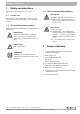
Safety considerations 1 Safety considerations Observe these instructions for your safety. 1.1 1.3 Observe the following guidelines RISK TO LIFE Correct use The conversion set is supplied for conversion of the GC124II/SP special gas-fired boiler from natural gas to propane. 1.2 1 through the explosion of volatile gases. WARNING! z Work on gas components must be carried out by qualified and authorized personnel only.
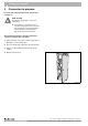
3 3 Conversion to propane Conversion to propane For your own safety read the instructions before conversion. RISK TO LIFE WARNING! through not observing the conversion instructions. z If you wish to convert the boiler for operation with propane, the conversion from natural gas to propane must be carried out first as specified by the attached conversion instructions. The following instructions must be followed for conversion of the boiler to propane: 1.
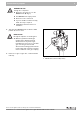
Conversion to propane 3 DANGER TO LIFE through fire or explosion. WARNING! z Never use excessive force on the ON/OFF knob (Î Fig. 2). z Turn ON/OFF knob only by hand. z Never use tools to turn knob. z If you are unable to turn the knob by hand, do not try to repair it. z Call Buderus technical service for assistance. 5. Turn gas valve ON/OFF knob clockwise to OFF position. Do not use force. RISK TO LIFE through the explosion of volatile gases.
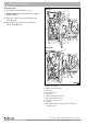
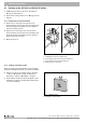
3 Conversion to propane Removing burner 5 GC124 II 7. Secure gas manifold with wire or cord. 8. GC124 II only: Remove igniter cable from ignition module (Î Fig. 3). 6 7 9. Disconnect cable connector from bottom of gas valve (Î Fig. 3). 8 9 10. Label cables to the flame roll-out switch, then remove cable (Î Fig. 3). 4 3 10 2 GC124 SP 1 5 8 9 4 3 2 Fig.
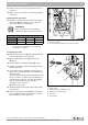
Conversion to propane 3 11. Remove four (4) screws from gas manifold on top of gas valve. 12. Remove two (2) screw nuts on burner tray and take out the tray. 2 Replacing main gas orifices 13. Install the new main gas orifices and copper gasket. Check with Î Tab. 1 that the correct orifices for operation of the boiler are installed. USER NOTE These orifice sizes are exclusively for installations 0-8500 feet above sea level. Orifice sizes for propane Model Orifice size Qty. Tab.
3 Conversion to propane Removing pilot burner and replacing pilot gas orifice 2 21. Unscrew ignition burner unit from burner. 4 22. Remove pilot orifice. 3 23. Position the new BBR 12 pilot gas orifice for the GC124 II or the new GAF 8 pilot gas orifice for the GC124 SP in pilot burner unit. 4 3 1 USER NOTE When installing the pilot gas orifice, make sure that the pilot gas orifice is correctly threaded and tightened. 24. Screw the pilot line to the pilot burner unit. 25.
Start-up instructions 4 4 Start-up instructions For your own safety, read before boiler start-up. RISK TO LIFE WARNING! due to not observing the start-up instructions and resulting malfunction. z If these instructions are not followed exactly, fire or explosion may result causing serious property damage, loss of life, or serious personal injury. z Observe the installation instructions.
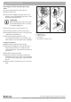
4 4.1 Start-up instructions Starting up the GC124 II and GC124 SP boilers 1. STOP! First perform a leak test as described on Î page 8 of this manual. 2. First read the safety instructions on Î page 9 of this manual. 4.1.1 Prepare pressure measurement 3. Remove the screw plug for the gas pressure measurement port on the gas valve. Install pressure measuring nipple and attach a pressure gauge to measure the gas pressure. 2 2 4.
Final start-up procedures for GC124 II models 5 5 Final start-up procedures for GC124 II models Verifying the ignition spark 1. Look through the sight glass at the igniter and verify that a spark is visible. 2. Should no spark be visible continue to troubleshooting procedure in the installation and service manual. 1 Fig. 9 1 GC124 II boile Sight glass RISK TO LIFE from fire or explosion. WARNING! z Never use excessive force on the ON/OFF knob (Î Fig. 10). z Turn ON/OFF knob only by hand.
5 Final start-up procedures for GC124 II models Checking gas supply pressure 5. Check the gas supply pressure while the boiler is operating. The connection pressure for natural gas must be between 4.7" and 10.5" W.C. For propane gas (LP) it must be between 11" and 13" W.C. If the gas pressure is in the correct range, record the measured value in the start-up protocol, then continue with step 6. If the supply pressure does not meet the above criteria, close gas line and contact the gas company.
Final start-up procedures for GC124 II models 5 8. Observe main burner flame through the sight glass (Î Fig. 9, page 11) in the burner plate. The flame must show a steady and stable body and generally be of bluish color. If the main burner flame meets the requirements, proceed to step 9. If the main burner flame is weak, yellow, or goes out, turn the ON/OFF knob (Î Fig. 13) on the gas valve clockwise to OFF.
5 Final start-up procedures for GC124 II models Checking for leaks 17. Open main gas shut-off. 18. Set thermostat at least 10°F above ambient to establish a heat demand. 19. Turn main power switch ON. 20. Turn gas valve ON/OFF knob counterclockwise to ON position. 21. After the burner has lit check the gas valve including screw plugs for leaks using soapy water. If no leaks are found, continue with step 23.
Final start-up procedures for GC124 II models 5 Checking aquastat Check the function of the maximum aquastat to make sure that it switches the boiler off as soon as the boiler water temperature set at the aquastat is reached. Record the result in the start-up protocol. 25. Set aquastat to its desired setting. 26. Replace front door and close. 1 Fig. 15 1 Checking aquastat Adjustment knob We reserve the right to make any changes due to technical modifications.
6 6 Final start-up procedure for GC124 SP models Final start-up procedure for GC124 SP models Lighting pilot RISK TO LIFE from fire or explosion. WARNING! z Never use excessive force on the ON/OFF knob (Î Fig. 17). z Turn ON/OFF knob only by hand. z Never use tools to turn knob. z If you are unable to turn the knob by hand, do not try to repair it. 1 z Call Buderus technical service for assistance. 2 Fig. 16 1 2 GC124 SP boiler Sight glass Thermocouple 1.
Final start-up procedure for GC124 SP models 6 8. If the ignition burner continues to go out after several attempts, turn the ON/OFF knob on the gas valve to OFF immediately to prevent gas from leaking. Check ignition gas line for leaks with soapy water. If no leaks are found, continue with step 9. If leaks have been found, turn ON/OFF knob on gas valve (Î Fig. 18) clockwise to the "OFF" position. 9. Seal leaks. Repeats steps 1 to 8. 10. The gas valve ON/OFF knob (Î Fig.
6 Final start-up procedure for GC124 SP models 16. Observe main burner flame through the sight glass (Î Fig. 16, page 16) in the burner plate. The flame must have a steady and fixed contour and generally has a bluish color. If the main burner flame meets the requirements, proceed with step 17. If the main burner flame is too weak or is yellow or goes out, turn the ON/OFF knob (Î Fig. 21) on the gas valve clockwise to OFF.
Final start-up procedure for GC124 SP models 6 Carrying out leak test 26. Open main gas shut-off. 27. Set thermostat at least 10°F above ambient to establish a heat demand. 28. Turn on ON/OFF switch (Emergency shutoff switch). 29. Repeat steps 1 to 5 on page 16. 30. After the burner has lit check the gas valve including screw plugs for leaks using soapy water. If no leaks are found, continue with step 32. If leaks are found, close gas valve and turn ON/OFF knob on gas valve clockwise to the OFF position.
6 Final start-up procedure for GC124 SP models Checking the Aquastat Check the function of the maximum aquastat to make sure that it switches the boiler off as soon as the boiler water temperature set at the aquastat is reached. Record the result in the start-up protocol. 34. Set the aquastat to its desired setting. 35. Replace front door and close. 1 Fig.
Final start-up procedure for GC124 SP models 6 We reserve the right to make any changes due to technical modifications.
Notes We reserve the right to make any changes due to technical 22 Instructions for conversion kit for gas boiler Logano GC124 II/SP • Issue 07/2006
Notes We reserve the right to make any changes due to technical modifications.
Your installer: BBT North America Corporation - Bosch Group 50 Wentworth Ave Londonderry, New Hampshire 03053 USA Tel: (603) 552-1100/800-Buderus Fax: (603) 421-2719 www.buderus.net BBT Thermotechnik GmbH, D-35573 Wetzlar www.heiztechnik.buderus.de info@heiztechnik.buderus.