7 747 000 512 – 07/2006 US For installers Installation and Service Instructions Gas boiler Logano GC124 II/SP CAUTION! Before placing this boiler in operation observe the safety instructions of this installation and maintenance manual. WARNING! Installation, adjustment, modification, operation or maintenance of the heating system carried out by unqualified personnel may result in property damage, personal injury, and loss of life.
Summary 1 Safety considerations 1.1 1.2 1.3 1.4 1.5 . . . . . . . . . . . . . . . . . . . . . . . . . . . . . . . . . . . . . . . . 4 Correct use . . . . . . . . . . . . . . Observe the following symbols . . Observe the following guidelines . Tools, materials and accessories Disposal . . . . . . . . . . . . . . . . . . . . . . . . . . . . . . . . . . . . . . . . . . . . . . . . . 4 . . . . . . . . . . . . . . . . . . . . . . . . . . . . . . . . . 4 . . . . . . . . . . . . . . . . . . . . . . . . . . . .
Summary 16 Boiler inspection and maintenance. . . . . . . . . . . . . . . . . . . . . . . . . . . . . . 43 16.1 Why is regular maintenance important? . . . . . . . . . . . . . . . . 16.2 Testing the flue system, including combustion air, air inlets and Ventilation openings . . . . . . . . . . . . . . . . . . . . . . . . . . . . 16.3 Inspection of the boiler and burner . . . . . . . . . . . . . . . . . . . 16.4 Preparing boiler for cleaning . . . . . . . . . . . . . . . . . . . . . . . 16.
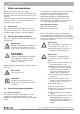
1 1 Safety considerations Safety considerations The burner and control must be correctly installed and adjusted to ensure safe and economical operation of the gas boiler. If specified by the local regulatory authorities the heating system must comply with the regulations of the "Standard for Controls and Safety Devices for Automatically Fired Boilers," ANSI/ASME CSD-1.
Safety considerations SYSTEM DAMAGE CAUTION! 1 1.3.3 Information on the boiler room due to incorrect installation. RISK TO LIFE z Observe all current standards and guidelines applicable to the installation and operation of the boiler heating system as applicable in your state or local jurisdiction. by poisoning. WARNING! z Make sure that inlets and outlets are not reduced in size or closed.
1 Safety considerations FIRE DANGER due to flammable materials or liquids. WARNING! z Make sure that there are no flammable materials or liquids in the immediate vicinity of the boiler. z Maintain a minimum distance of 15 inches from the boiler. 1.4 Tools, materials and accessories You need standard tools for the installation and maintenance of the boiler as used in boiler heating system installation and oil, gas and water installations.
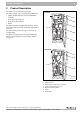
Product Description 2 2 Product Description The boiler is a low temperature gas boiler. GC124 II The boiler consists of the following main components: – Ignition module (GC124 II only) and adjustable aquastat 1 – Boiler jacket and front door 2 – Boiler block with insulation – Burner The ignition module and adjustable aquastat monitor and control all electrical and operational components of the boiler. 3 6 The boiler jacket prevents energy loss and acts as soundproofing.
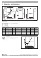
3 Dimensions and Connections 3 Dimensions and Connections 2 3/8 VK 1¼" GAS ½" EL ¾" Fig. 2 (GAS ½")* RK 1¼" Back, side and front view, measurements in inches * optional connection Connections (measurements see the following tables): VK = Boiler supply RK = Boiler return EL = Boiler drain GAS = Gas connection Boiler size Boiler input A B Vent connection II/SP Min. relief valve capacity Number of Orifices Water volume Dry weight Btu/hr Inches Inches Inches lb/hr Qty. US Gal.
Scope of delivery 4 4 Scope of delivery z Check packaging upon receipt of delivery for damage. z Check delivery for completeness.
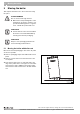
5 5 Moving the boiler Moving the boiler This chapter describes how to move the boiler safely into place. SYSTEM DAMAGE Due to uneven and rough surfaces. CAUTION! z Observe the transport diagrams on the packaging to protect the sensitive components from damage due to rough surfaces. Handle the product with care. USER NOTE z Protect all boiler connections from dirt if the boiler is not installed immediately following removal from packaging.
Moving the boiler 5 RISK OF INJURY CAUTION! due to improper securing of the boiler during transport. z Use a boiler coart or dolley and strap for moving the boiler z Secure boiler on the boiler cart. z Remove the front door during lifting or transport to prevent unintentional opening. z Set the boiler cart or dolley on the front side of the boiler and put a piece of cardboard between the two to prevent scratches. 1 z Secure boiler on the boiler cart. z Move boiler to desired location.
6 6 Placing the boiler Placing the boiler This chapter explains how to place the boiler and position it in the boiler room. SYSTEM DAMAGE due to frost. CAUTION! z Place the boiler in a frost-free room. The boiler is very heavy when filled with water. Check that the floor can bear the weight before installation. 6.1 Clearances The GC124 boiler is approved for closet installation.
Boiler installation 7 7 Boiler installation This chapter describes how to install the boiler. This includes the following tasks: – Connecting the heating system – Electrical connection – Gas supply piping connection 7.1 Preparing for installation z Unpack all boxes and containers and check all parts against the packing lists to make sure that everything has been supplied. USER NOTE Every boiler is carefully inspected and tested before it leaves the factory.
7 7.2 Boiler installation Connecting the heating system BOILER DAMAGE Due to moisture. CAUTION! 3 z Protect the components of the gas ignition system from moisture (dripping, spray, rain) during installation of the boiler, during operation and during maintenance work (such as replacing the pump, replacing the control, etc.). SYSTEM DAMAGE CAUTION! 2 1 Due to overheating as a result of a low water condition.
Boiler installation 7 Installation of B-kit The relief valve and the pressure/temperature gauge are mounted on the boiler supply manifold which is attached to the VK (supply) connection of the boiler (included in B-kit). 1 Installing boiler supply VK: 2 z Remove factory installed plastic inserts from boiler supply (VK), boiler return (RK) and boiler drain (EL) connections.
7 Boiler installation FIRE DANGER due to exposure to hot water pipes. CAUTION! 7.3 z Maintain a minimum clearance of two inches between non-insulated pipes carrying hot water and combustible walls and surfaces in the boiler room. A minimum of 1" high quality pipe insulation is required to permit direct contact with combustible surfaces.
Boiler installation 7 Description of field installed wiring connections using factory supplied junction box. z Remove two knock-outs from the left side of boiler panel to route electrical feed and pump power into junction box. z Route electrical power from the outside into junction box. 1 z Install a metal strain relief for the incoming power line on outside of left boiler jacket panel. (Î Fig. 12). z Just use supplied wiring nuts and double proper wiring before powering up the boiler.
7 Boiler installation 7.4 Fuel gas supply connection 7.4.1 Gas connections For the gas pipe diameter required for the installation please see Î Tab. 4 and Î Tab. 5. Make sure that the pipe fitting has the correct thread size. 1 Make sure that a sediment trap is installed at the inlet for the gas supply pipe to the boiler. A manual stop valve must be installed outside the boiler jacket if required by the local code. We recommend installing a manual shut-off valve in the main gas pipe to the boiler.
Boiler installation 7 Disconnect the boiler with the manual shut-off valve and physically separate the boiler from the gas piping if the gas piping system is pressure tested with a test pressure greater than 1/2 psi. If the gas supply pipe system is pressure tested at a test pressure of 1/2 psi or less, it is sufficient to disconnect the boiler from the gas pipe system by closing the manual shut-off valve. Use only sealant that is resistant to corrosion by LPG for pipe connection.
7 7.5 Boiler installation Filling heating system and checking for leaks The boiler is tested for leaks at the factory. Before placing the heating system into use, check the entire system for soundness to avoid leaks occurring during operation. Water treatment USER NOTE Have the water analyzed before filling the heating system. The water may require treatment as a result of the analysis. Please consult the local water supply company if the water is extremely hard or has a pH level below 7.0.
Boiler installation 7 z Close connection for relief valve (Î Fig. 14) and all other open connections with plugs. z Disconnect the expansion tank from the system by closing the expansion tank shut-off valve. z Open mixing and shut-off valves on hot water side. 1 z Fill boiler slowly with water from the feed water connection. z Open automatic vents slightly to allow the air to escape. z Slowly fill heating system. Observe pressure display on pressure gauge during this process.
8 8 Check openings for combustion air supply and venting Check openings for combustion air supply and venting BOILER DAMAGE AND OPERATING FAULTS CAUTION! z If faults are not corrected immediately, the boiler must not be operated Make sure that the boiler room has two permanent openings that are connected with one or more other rooms. When calculating the cross-section areas of the openings, the total combustion output of all gas-fired appliances in the connected rooms must be taken into account.
Requirements for connection to chimneys or venting systems 9 9 Requirements for connection to chimneys or venting systems The flue connection must comply with the regulations of the National Fuel Gas Code, Part 7, Venting of Equipment, and the local construction codes. Flue connections of heating systems with natural venting must not be connected with any component of a mechanically operated venting system that operates with overpressure.
10 Flue pipe installation 10 Flue pipe installation This section describes the connection of the flue pipe and venting system. Note that the open draft hood cannot be modified under any circumstances. 5 USER NOTE 4 z The boiler can and may only be operated with the electrical vent damper that is standard supplied with every GC124. 3 6 2 7 1. The flue collar is factory installed on the flue connection of the open draft hood and fastened with four (4) corrosion-resistant sheet metal screws.
Flue pipe installation 10 A minimum clearance of six inches is required between the flue pipes and all flammable materials. The vent pipe must not be reduced in size and the venting system must not be compromised by the installation of additional appliances. Electrically connecting the vent damper 5. Disconnect your heating system from the main electricity supply. 6. Route the connection wiring of the vent damper along the left side of the boiler into the opening on the left side of the boiler.
11 Placing the heating system in operation 11 Placing the heating system in operation The burner and gas train integrated in the boiler have been tested at the factory as described in ANSI Z 21.13 to ensure safe operation of the heating system and verify specific performance indicators. RISK TO LIFE due to electric shock when the cover protecting the electric components has WARNING! been removed.
Placing the heating system in operation 11 Verifying the appliance Boiler size Natural gas LP Tab. 7 Main gas orifice identification 18 25 32 285 275 270 180 175 170 Main gas orifice identification. These parts are only valid for the U.S.A. from 0-8500ft in elevation. 3. Fill heating system and bleed the complete system including all radiators and zones. 4. Open front door (Î Fig. 19). Testing gas train for leaks 5. Open gas manual shut off in the gas line. 6.
11 Placing the heating system in operation For your own safety, read before boiler start-up. RISK TO LIFE WARNING! due to not observing the start-up instructions and resulting malfunction. z If these instructions are not followed exactly, fire or explosion may result causing serious property damage, loss of life, or serious personal injury. z Observe the installation instructions.
Placing the heating system in operation 11 11.1 Starting up the GC124 II and GC124 SP boilers 1. STOP! First perform a leak test as described on Î page 27 of this manual. 2. First read the safety instructions on Î page 28 of this manual. 11.1.1 Prepare pressure measurement 3. Remove the screw plug for the gas pressure measurement port on the gas valve. Install pressure measuring nipple and attach a pressure gauge to measure the gas pressure. 2 2 4.
12 Final start-up procedures for GC124 II models 12 Final start-up procedures for GC124 II models Verifying the ignition spark 1. Look through the sight glass at the igniter and verify that a spark is visible. 2. Should no spark be visible continue to troubleshooting in Î Chapter 16.8, page 55. 1 Fig. 22 1 GC124 II boile Sight glass RISK TO LIFE from fire or explosion. WARNING! z Never use excessive force on the ON/OFF knob (Î Fig. 23). z Turn ON/OFF knob only by hand.
Final start-up procedures for GC124 II models 12 Checking gas supply pressure 5. Check the gas supply pressure while the boiler is operating. The connection pressure for natural gas must be between 4.7" and 10.5" W.C. For propane gas (LP) it must be between 11" and 13" W.C. If the gas pressure is in the correct range, record the measured value in the start-up protocol, then continue with step 6. If the supply pressure does not meet the above criteria, close gas line and contact the gas company.
12 Final start-up procedures for GC124 II models 8. Observe main burner flame through the sight glass (Î Fig. 22, page 30) in the burner plate. The flame must show a steady and stable body and generally be of bluish color. If the main burner flame meets the requirements, proceed to step 9. If the main burner flame is weak, yellow, or goes out, turn the ON/OFF knob (Î Fig. 26) on the gas valve clockwise to OFF.
Final start-up procedures for GC124 II models 12 Checking for leaks 17. Open main gas shut-off. 18. Set thermostat at least 10°F above ambient to establish a heat demand. 19. Turn main power switch ON. 20. Turn gas valve ON/OFF knob counterclockwise to ON position. 21. After the burner has lit check the gas valve including screw plugs for leaks using soapy water. If no leaks are found, continue with step 23.
12 Final start-up procedures for GC124 II models Checking aquastat Check the function of the maximum aquastat to make sure that it switches the boiler off as soon as the boiler water temperature set at the aquastat is reached. Record the result in the start-up protocol. 25. Set aquastat to its desired setting. 26. Replace front door and close. 1 Fig. 28 1 Checking aquastat Adjustment knob We reserve the right to make any changes due to technical modifications.
Final start-up procedure for GC124 SP models 13 13 Final start-up procedure for GC124 SP models Lighting pilot RISK TO LIFE from fire or explosion. WARNING! z Never use excessive force on the ON/OFF knob (Î Fig. 23). z Turn ON/OFF knob only by hand. z Never use tools to turn knob. z If you are unable to turn the knob by hand, do not try to repair it. 1 z Call Buderus technical service for assistance. 2 Fig. 29 1 2 GC124 SP boiler Sight glass Thermocouple 1.
13 Final start-up procedure for GC124 SP models 8. If the ignition burner continues to go out after several attempts, turn the ON/OFF knob on the gas valve to OFF immediately to prevent gas from leaking. Check ignition gas line for leaks with soapy water. If no leaks are found, continue with step 9. If leaks have been found, turn ON/OFF knob on gas valve (Î Fig. 31) clockwise to the "OFF" position. 9. Seal leaks. Repeats steps 1 to 8. 10. The gas valve ON/OFF knob (Î Fig.
Final start-up procedure for GC124 SP models 13 16. Observe main burner flame through the sight glass (Î Fig. 29, page 35) in the burner plate. The flame must have a steady and fixed contour and generally has a bluish color. If the main burner flame meets the requirements, proceed with step 17. If the main burner flame is too weak or is yellow or goes out, turn the ON/OFF knob (Î Fig. 34) on the gas valve clockwise to OFF.
13 Final start-up procedure for GC124 SP models Carrying out leak test 26. Open main gas shut-off. 27. Set thermostat at least 10°F above ambient to establish a heat demand. 28. Turn on ON/OFF switch (Emergency shutoff switch). 29. Repeat steps 1 to 5 on page 35. 30. After the burner has lit check the gas valve including screw plugs for leaks using soapy water. If no leaks are found, continue with step 32. If leaks are found, close gas valve and turn ON/OFF knob on gas valve clockwise to the OFF position.
Final start-up procedure for GC124 SP models 13 Checking the Aquastat Check the function of the maximum aquastat to make sure that it switches the boiler off as soon as the boiler water temperature set at the aquastat is reached. Record the result in the start-up protocol. 34. Set the aquastat to its desired setting 35. Replace front door and close 1 Fig. 36 1 Checking aquastat Adjustment knob We reserve the right to make any changes due to technical modifications.
14 Start-up protocol 14 Start-up protocol Please check off all startup steps and record measurements in the appropriate tables. Start-up procedure Remarks or measured values 1. Type of gas Natural gas LP 2. Has the leak test been completed? 3. Check combustion air, inlet and outlet openings and flue gas connection 4. Check the equipment (correct orifices? See below) and convert gas type if necessary 5. Fill boiler with water and bleed complete heating system 6.
Start-up protocol 14 14.1 Informing the owner/operator and handing over technical documentation Inform the owner/operator of the operation of the complete heating system and the operating instructions for the boiler. The heating contractor shall instruct and demonstrate the start-up and shut-down procedure of the boiler to the owner/operator. Please instruct the owner/operator how to proceed in case of a fire. Sign the protocol on Î page 40 with the owner and hand over the technical documentation.
15 Taking the heating system out of operation 15 Taking the heating system out of operation 15.1 Normal system shut-down 1. Turn ON/OFF switch (emergency shutoff switch) to OFF position. This shuts off power to the boiler and all of its components (e.g. burner, aquastat). 2. Turn ON/OFF knob on gas valve clockwise to OFF position. SYSTEM DAMAGE due to freezing. CAUTION! The heating system can freeze up in cold weather if it is shut down.
Boiler inspection and maintenance 16 16 Boiler inspection and maintenance 16.1 Why is regular maintenance important? Heating systems require regular maintenance for the following reasons: – to maintain high efficiency operation and to operate the heating system economically (low fuel consumption), – to sustain safe operation, – to maintain combustion at an environmentally responsible level. – to ensure trouble-free operation and long life.
16 Boiler inspection and maintenance 16.4 Preparing boiler for cleaning 1. Take the boiler out of operation (Î Chapter 15.1, page 42). RISK TO LIFE from electric shock. WARNING! z Before opening a unit: disconnect electrical power and lock to prevent accidental reactivation. 2. Open and remove front door of boiler (Î Fig. 19, page 27). RISK TO LIFE from explosion of flammable gases. WARNING! z Never work on gas lines unless you are licensed for this type of work 3.
Boiler inspection and maintenance 16 16.5 Cleaning the boiler The boiler can be cleaned with brushes and/or by wet cleaning. Cleaning tools are available as accessories. Inspecting the ignition burner of the GC124 II 1. Observe the ignition burner through the sight glas (Î Fig. 39). 1 Fig. 39 1 GC124 II boiler Sight glass 2. The flame must rise over the sensor by ½" to 1-½". 1 3. The pilot ignition gas pressure must be adjusted if the flame is too small or too large.
16 Boiler inspection and maintenance 4. Remove the safety screw on the adjustment screw for the igniter (Î Fig. 41).Turn the inner adjustment screw clockwise to reduce the size of the ignition flame, and counterclockwise to increase it. 5. After completed adjustment replace the safety screw (Î Fig. 41). 6. If the flame is too small, the pilot orifice needs cleaning (Î Fig. 50, page 51). If the igniter flame is acceptable, start cleaning.
Boiler inspection and maintenance 16 10. Remove protective screw on adjustment screw for pilot burner (Î Fig. 44) Turn inner screw clockwise to reduce the size of the pilot burner flame. Turn the inner screw counterclockwise to increase the pilot burner flame. 11. After completed adjustment replace the safety screw (Î Fig. 44). 12. If the flame is too small, the pilot orifice needs cleaning (Î Fig. 44). If the pilot flame is acceptable, start cleaning.
16 Boiler inspection and maintenance 15. Secure gas manifold with wire or cord. 5 GC124 II 16. GC124 II only: Remove igniter cable from ignition module (Î Fig. 45). 6 7 17. Disconnect cable connector from bottom of gas valve (Î Fig. 45). 8 9 18. Label cables to the flame roll-out switch, then remove cable. (Î Fig. 45). 4 3 10 2 GC124 SP 1 5 8 9 4 3 2 Fig.
Boiler inspection and maintenance 16 19. Remove four (4) screws from gas manifold on top of gas valve. 20. Remove two (2) screw nuts on burner tray and take out the tray. 2 1 Fig. 46 1 2 Removing burner (GC124 SP shown) Screw nuts (two) Screws on gas manifold on top of gas valve (four) 21. Remove 4 screws on sides of the top cover and lift off. Fig. 47 Remove top cover We reserve the right to make any changes due to technical modifications.
16 Boiler inspection and maintenance 22. Remove top boiler insulation. 23. Unscrew cleaning cover from the venting manifold. 24. Cover control with foil to prevent entry of metal dust into the control. 1 1 2 2 25. Use boiler brush to clean out flue gas passages. 26. Clean combustion chamber and bottom insulation. 27. Replace cleaning cover, install screws, and replace insulation. 16.5.
Boiler inspection and maintenance 16 16.6 Cleaning the burner 1. Remove burner (Î page 47). 2. Check burner rods for dirt. If necessary, clean burner as described below. 3. Unscrew ignition burner unit from burner. 2 5 4. Disconnect ignition gas line from ignition burner unit. 5. Remove ignition gas jet and blow out. 4 6. Immerse burner rods in water with cleaning agent and brush off. 3 USER NOTE 4 3 1 Be careful not to damage the pilot orifice during installation and cleaning.
16 Boiler inspection and maintenance Performing final checks 14. Place boiler in operation as directed in Î Chapter 11, page 26 to page 29. 15. For GC124 II: Follow instructions in Î Chapter 12, page 30 to page 34. 16. For GC124 SP: Follow instructions inÎ Chapter 13, page 35 bis page 39. 17. Test low water alarm if installed. 18. Check area around boiler for hazards. RISK OF FIRE From flammable material or liquids.
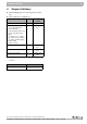
Boiler inspection and maintenance 16 16.7 Maintenance protocol Please check off the maintenance work as it is completed and record the measured values. Follow the instructions on the following pages. Maintenance work Page Date: Date: 1. Inspection of the flue system including combustion air, inlet and outlet openings page 43 2. Inspection of boiler Gas manifold pressure page 43 page 21 3. Inspection of burner page 43 4. Cleaning of boiler page 45 5. Cleaning of burner page 51 6.
16 Boiler inspection and maintenance Datum: Datum: Datum: Datum: Datum: –––––––inches W. C –––––––inches W. C –––––––inches W. C –––––––inches W. C –––––––inches W. C –––––––inches W. C –––––––inches W. C –––––––inches W. C –––––––inches W. C –––––––inches W. C We reserve the right to make any changes due to technical modifications.
Boiler inspection and maintenance 16 16.8 Troubleshooting the GC124 II Equipment required: Wiring diagrams (Î Chapter 19, page 80) and voltage detectors for 120 VAC and 24 VAC. Start Close gas shut-off. Set thermostat (control) to require heat (vent damper open). Switch on power. No Observe ignition sparks in gap between electrode and sensor through sight glass. No • Check electrical power source, low-voltage transformer, thermostat (control) and wiring.
16 Boiler inspection and maintenance START PHASE 1 Ignition attempt Room thermostat (control) signals heat requirement Vent damper opens. Ignition spark generator operates • ignition gas valve opens. Ignition burner operation Ignition flame burns, automatic or ignition flame does not burn, auignition signals steady ignition tomatic ignition starts ignition atflame. tempt, switches off after 90 seconds. Pilot flame stand by • ignition spark generator stops. • main gas solenoid valve opens.
Boiler inspection and maintenance 16 16.9 Troubleshooting the GC124 SP Equipment required: Wiring diagrams (Î Chapter 19, page 80) and voltage detectors for 120 VAC and 24 VAC. Start Set gas valve ON/OFF knob clockwise to OFF position. Close main gas shut-off. Set thermostat (control) to heat requirement (vent damper opens). Switch on power. No Set gas valve ON/OFF knob counterclockwise to PILOT position. Open main gas shut-off. Press red pilot ignition button and ignite ignition flame.
16 Boiler inspection and maintenance Pilot burner operation continues evenly Thermocouple monitors ignition flame, ignition flame generates voltage in thermocouple and keeps ignition valve open. Start Room thermostat (control) signals heat requirement Vent damper opens. Main burner operating Main burner operation • thermocouple controls ignition flame. • main gas solenoid valve opens. Power interruption System switches off.
Parts lists 17 17 Parts lists The following spare parts are available for Buderus heating systems. The Buderus article number is listed in the column of the corresponding model if different parts are required for different models. In other cases the quantity of components is shown. Boiler jacket (Î Fig. 52) Item.
17 Parts lists 180 70 180 180 120 160 50 140 180 180 150 80 180 160 100 180 130 110 40 180 20 180 90 Bu Lo de ga no ru Cla ss s 170 ic 30 180 160 10 60 7747100028-01-Verkleidung GC124 US Fig. 52 Boiler jacket We reserve the right to make any changes due to technical modifications.
Parts lists 17 Boiler block – attachment parts (Î Fig. 53) Item. No.
17 Parts lists Boiler block – attachment parts (Î Fig. 53) Item. No. Description Buderus Part number Model 18 Quantity/ Model Model 25 Quantity/ Model Model 32 Quantity/ Model 270 BOILER DRAIN VALVE – ¾" NPT - 1 1 1 280 TRIDICATOR - 1 1 1 290 RELIEF VALVE ¾" M x F NPT - 1 1 1 7747000912 1 1 1 Mounting material Tab. 11 Boiler block mounting material We reserve the right to make any changes due to technical modifications.
Parts lists 17 180 150 150 200 201 140 110 110 290 170 260 210 120 130 12 270 12 280 110 240 110 220 205 90 100 100 90 100 110 100 13 250 100 110 60 50 230 10 30 60 50 160 190 11 14 14 60 11 100 15 15 40 60 50 80 40 40 20 40 50 7747100027-01-Kesselblock Anbauteile GC124 US Fig. 53 Boiler block mounting material We reserve the right to make any changes due to technical modifications.
17 Parts lists Control panel assembly for GC124 II (Î Fig. 54) Item. No.
Parts lists 17 Control panel assembly for GC124 II (Î Fig. 54) Item. No. Description Buderus Part number Model 18 Quantity/ Model Model 25 Quantity/ Model Model 32 Quantity/ Model 280 Angle bracket - 1 1 1 290 Wiring harness 7747004671 1 1 1 300 Junction box 7747004455 1 1 1 63015810 1 1 1 Mounting material Tab. 12 Controls for GC124 II We reserve the right to make any changes due to technical modifications.
17 Parts lists 300 10 11 12 290 280 240 270 270 260 20 220 250 230 30 210 30 200 230 40 190 50 60 70 50 180 60 80 90 150 90 160 50 60 60 50 170 110 110 100 60 60 50 7747100019-01-Regelung GAW030 US Fig. 54 Controls for GC124 II We reserve the right to make any changes due to technical modifications.
Parts lists 17 Control panel assembly for GC124 SP (Î Fig. 55) Item. No.
17 Parts lists 270 10 11 12 260 250 210 240 240 230 20 220 30 190 200 30 180 200 40 170 50 60 70 160 50 60 80 90 130 90 140 50 60 60 50 150 60 60 50 7747100020-01-Regelung GAW031 US Fig. 55 Controls for GC124 SP We reserve the right to make any changes due to technical modifications.
Parts lists 17 Burner assembly for GC124 II/SP (Î Fig. 56) Item. No.
17 Parts lists 10 11 12 20 30 110 70 70 70 70 50 90 100 60 60 50 40 60 60 80 81 82 83 84 85 7747100077-01-Brennrost AE124GC II/SP US Fig. 56 Burner for GC124 II/SP We reserve the right to make any changes due to technical modifications.
Parts lists 17 USER NOTE The complete burner is supplied only in the model for natural gas G20 for 0-8500 feet. If a different model of burner is wanted, the corresponding gas conversion parts must be included in the order. The replaced parts must remain with the heating system for a possible future reconversion. Complete Propane conversion kits (Î Fig. 57) Item. No.
17 Parts lists 10 11 12 20 21 22 7747100076-01-Brennervarianten, Gasartumstellteile AE124GC II/SP US Fig. 57 Gas conversion kits We reserve the right to make any changes due to technical modifications.
Parts lists 17 Gas valve GC124 II/SP (Î Fig. 58) Item. No. Description Buderus Part number Model 18 Quantity/ Model Model 25 Quantity/ Model Model 32 Quantity/ Model 10 Gas Supply Pipe elbow ½" NPT incl. gasket and screws 00475908 1 1 1 20 Gas valve VR8204H1006 GC124 II 00475825 1 1 1 25 Gas valve VR8200H1004 GC124 SP 05181446 1 1 1 30 Gasket 05483082 1 1 1 40 Screw for gas valve 63025928 1 1 1 Tab.
17 Parts lists 10 20 25 30 40 40 7747100078-02-Gasarmatur VR8204H 1006 GC124 II US Fig. 58 Gas valve GC124 II/SP We reserve the right to make any changes due to technical modifications.
Parts lists 17 Ignition burner GC124 II (Î Fig. 59) Item. No.
17 Parts lists 20 30 10 50 20 30 40 50 60 70 40 41 60 70 50 50 80 7747100080-00-Zündbrenner GC124 Classic II US Fig. 59 Ignition burner GC124 II We reserve the right to make any changes due to technical modifications.
Parts lists 17 Ignition burner GC124 SP (Î Fig. 60) Item. No.
17 Parts lists 20 30 20 50 10 20 30 40 50 60 70 40 41 60 50 70 50 80 90 7747100081-00-Zündbrenner GC124 Classic SP US Fig. 60 Ignition burner GC124 SP We reserve the right to make any changes due to technical modifications.
Technical specifications 18 18 Technical specifications Main gas orifice identification and manifold pressure for Natural gas Boiler size Number of orifices Main gas orifice identification for elevations from [feet] Gas supply volume [in ft3/h] Manifold pressure [inch W.C.] 68.8 95.8 123.3 3.5 3.5 3.5 0–8500 ft1) 18/3 25/4 32/5 2 3 4 285 275 270 Tab. 19 Main gas orifice identification and manifold pressure for Natural gas at60° F / 30 inch HG. These values are only valid in the U.S.A.
US 1 H N Service Switch (by others) Circulator white yellow Wiring diagram gas-boiler GC124 USA Intermittent ignition Junction Box black white yellow green white 120V 24V blue yellow C1 G L2X black B2 C Transformer 40VA B1 R black L1 C2 L2 L1X Blocked vent switch R Terminals on boiler block black orange PV MV Edition : 63046156 Drwg. no.: Main valve MV 24V AWG 18 WIRE 120 VAC Intermittent pilot dual valve combination gas control VR8204...
US 1 H N Service Switch (by others) Circulator white yellow Installation and maintenance instructions Gas Boiler Logano GC124 II/SP • Issue 07/2006 blue Standing pilot Wiring diagram gas-boiler GC124 USA Junction Box black white yellow green white 120V 24V yellow C1 G L2X black B2 C Transformer 40VA B1 R black L1 C2 L2 L1X Blocked vent switch R black Terminals on boiler block black orange Drwg. no.: Reviewed : Aquastat Relay L7148F...
19 Electrical circuit diagrams Fig. 63 Wiring Diagram– GC124 II Fig. 64 Wiring Diagram– GC124 SP We reserve the right to make any changes due to technical modifications.
Notes We reserve the right to make any changes due to technical modifications.
Your installer: BBT North America Corporation - Bosch Group 50 Wentworth Ave Londonderry, New Hampshire 03053 USA Tel: (603) 552-1100/800-Buderus Fax: (603) 421-2719 www.buderus.net BBT Thermotechnik GmbH, D-35573 Wetzlar www.heiztechnik.buderus.de info@heiztechnik.buderus.